How to Use Spectrscopy Sensor AS7265x: Examples, Pinouts, and Specs
Introduction
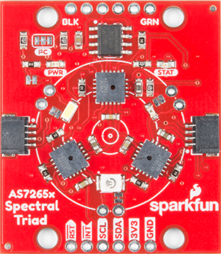
The AS7265x is a multi-channel spectral sensor designed to capture light in the visible spectrum and provide digital output for color and spectral analysis. This sensor is part of a family of advanced spectral sensing devices, offering high precision and flexibility for a wide range of applications. The AS7265x integrates three sensors (AS72651, AS72652, and AS72653) to cover 18 individual spectral channels, making it ideal for applications requiring detailed spectral data.
Explore Projects Built with Spectrscopy Sensor AS7265x


Explore Projects Built with Spectrscopy Sensor AS7265x
Common Applications
- Color Detection: Used in industrial and consumer applications for accurate color matching.
- Material Identification: Enables identification of materials based on their spectral signatures.
- Environmental Monitoring: Measures light properties for applications such as agriculture, water quality, and air quality analysis.
- Scientific Research: Provides spectral data for experiments and studies in physics, chemistry, and biology.
Technical Specifications
The AS7265x is a highly capable spectral sensor with the following key specifications:
| Parameter | Value |
|---|---|
| Spectral Channels | 18 (410 nm to 940 nm, 20 nm resolution) |
| Communication Interface | I²C and UART |
| Supply Voltage | 2.7V to 3.6V |
| Operating Current | ~20 mA (active mode) |
| Standby Current | ~2 µA |
| Operating Temperature | -40°C to +85°C |
| Package | LGA-28 (AS72651), LGA-20 (AS72652/AS72653) |
Pin Configuration and Descriptions
The AS7265x module typically includes three interconnected sensors. Below is the pin configuration for the primary sensor (AS72651):
| Pin | Name | Description |
|---|---|---|
| 1 | VDD | Power supply (2.7V to 3.6V) |
| 2 | GND | Ground |
| 3 | SCL | I²C clock line |
| 4 | SDA | I²C data line |
| 5 | TX | UART transmit |
| 6 | RX | UART receive |
| 7 | INT | Interrupt output |
| 8 | GPIO1 | General-purpose I/O |
| 9 | GPIO2 | General-purpose I/O |
| 10 | LED_CTRL | LED control output |
For the secondary sensors (AS72652 and AS72653), the pinout is similar but excludes I²C and UART pins, as they communicate internally with the primary sensor.
Usage Instructions
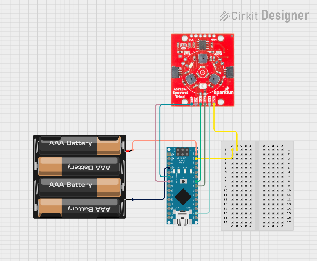
How to Use the AS7265x in a Circuit
- Power Supply: Connect the VDD pin to a 3.3V power source and GND to ground.
- Communication Interface:
- For I²C communication, connect the SCL and SDA pins to the corresponding pins on your microcontroller. Use pull-up resistors (typically 4.7 kΩ) on both lines.
- For UART communication, connect the TX and RX pins to the UART pins on your microcontroller.
- Interrupts and GPIO: Use the INT pin to detect data-ready signals. GPIO pins can be configured for additional functionality.
- LED Control: Connect an external LED to the LED_CTRL pin if illumination is required for spectral measurements.
Best Practices
- Calibration: Perform a calibration procedure to ensure accurate spectral readings. Use a known light source or reference material for calibration.
- Avoid Noise: Place decoupling capacitors (e.g., 0.1 µF) near the VDD pin to reduce power supply noise.
- Ambient Light: Minimize ambient light interference by using an optical enclosure or shield.
- Data Rate: Adjust the integration time and gain settings to optimize the signal-to-noise ratio for your application.
Example Code for Arduino UNO
Below is an example of how to interface the AS7265x with an Arduino UNO using I²C communication:
#include <Wire.h>

// AS7265x I2C address
#define AS7265X_I2C_ADDR 0x49

void setup() {
  Wire.begin(); // Initialize I2C communication
  Serial.begin(9600); // Initialize serial communication for debugging

  // Configure the AS7265x
  configureAS7265x();
}

void loop() {
  // Read spectral data
  uint8_t spectralData[18];
  readSpectralData(spectralData);

  // Print spectral data to the serial monitor
  Serial.println("Spectral Data:");
  for (int i = 0; i < 18; i++) {
    Serial.print("Channel ");
    Serial.print(i + 1);
    Serial.print(": ");
    Serial.println(spectralData[i]);
  }

  delay(1000); // Wait 1 second before the next reading
}

void configureAS7265x() {
  // Example configuration: Set integration time and gain
  Wire.beginTransmission(AS7265X_I2C_ADDR);
  Wire.write(0x04); // Integration time register
  Wire.write(0xFF); // Maximum integration time
  Wire.endTransmission();

  Wire.beginTransmission(AS7265X_I2C_ADDR);
  Wire.write(0x05); // Gain register
  Wire.write(0x03); // Maximum gain
  Wire.endTransmission();
}

void readSpectralData(uint8_t *data) {
  Wire.beginTransmission(AS7265X_I2C_ADDR);
  Wire.write(0x08); // Data register
  Wire.endTransmission();

  Wire.requestFrom(AS7265X_I2C_ADDR, 18); // Request 18 bytes of data
  for (int i = 0; i < 18; i++) {
    if (Wire.available()) {
      data[i] = Wire.read();
    }
  }
}
Troubleshooting and FAQs
Common Issues
No Communication with the Sensor
- Cause: Incorrect I²C address or wiring.
- Solution: Verify the I²C address (default is 0x49) and check all connections.
Inaccurate Spectral Readings
- Cause: Calibration not performed or incorrect integration time.
- Solution: Perform a proper calibration and adjust the integration time and gain.
Ambient Light Interference
- Cause: Excessive ambient light affecting measurements.
- Solution: Use an optical enclosure or shield to block ambient light.
Sensor Not Responding
- Cause: Insufficient power supply or incorrect voltage levels.
- Solution: Ensure the VDD pin is supplied with 3.3V and check for stable power.
FAQs
Q: Can the AS7265x measure UV or IR light?
A: The AS7265x primarily measures visible light (410 nm to 940 nm). For UV or IR measurements, consider other sensors in the AS72xx family.
Q: How do I increase the accuracy of measurements?
A: Use proper calibration, minimize ambient light interference, and optimize integration time and gain settings.
Q: Can I use the AS7265x with a 5V microcontroller?
A: Yes, but you must use a level shifter to convert the 5V logic levels to 3.3V for I²C or UART communication.
Q: What is the maximum I²C speed supported?
A: The AS7265x supports I²C speeds up to 400 kHz (Fast Mode).