Cirkit Designer Logo
Cirkit Designer
Your all-in-one circuit design IDE
Home / 
Component Documentation

How to Use XM125 Sparkfun: Examples, Pinouts, and Specs

Image of XM125 Sparkfun
Cirkit Designer LogoDesign with XM125 Sparkfun in Cirkit Designer

Introduction

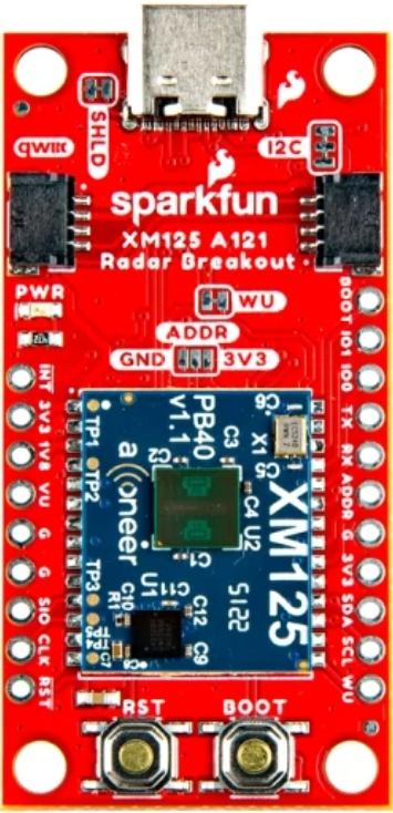
The XM125 is a GPS module from Sparkfun designed to provide accurate and reliable positioning data. With its compact design and low power consumption, the XM125 is ideal for applications where space and energy efficiency are critical. This module is widely used in robotics, drones, vehicle tracking, and other GPS-based systems. Its ease of integration and robust performance make it a popular choice for both hobbyists and professionals.

Explore Projects Built with XM125 Sparkfun

Use Cirkit Designer to design, explore, and prototype these projects online. Some projects support real-time simulation. Click "Open Project" to start designing instantly!
Remote-Controlled Drone with Motion Sensing Capabilities
Image of melty: A project utilizing XM125 Sparkfun in a practical application
This circuit is designed for motion control and telemetry in a small vehicle or drone. It includes an Adafruit ADXL345 accelerometer interfaced with a SparkFun Pro Micro microcontroller for motion sensing. The circuit also features two Electronic Speed Controllers (ESCs) to drive motors, a step-up voltage regulator to stabilize power supply from a Lipo battery, and a flysky mini receiver to receive control signals from a remote transmitter.
Cirkit Designer LogoOpen Project in Cirkit Designer
ESP32-Based Motion Tracking System with ICM20948 Sensor
Image of ICM20948: A project utilizing XM125 Sparkfun in a practical application
This circuit features a SparkFun ESP32 Thing Plus microcontroller interfaced with an Adafruit ICM20948 9-axis motion sensor via an Adafruit TXB0104 4-channel bi-directional level shifter. The ESP32 reads data from the ICM20948 sensor, calculates orientation angles such as pitch, roll, yaw, and azimuth, and outputs these values to the serial monitor. The level shifter ensures compatibility between the 3.3V logic levels of the ESP32 and the 1.8V logic levels required by the ICM20948.
Cirkit Designer LogoOpen Project in Cirkit Designer
Bluetooth-Controlled Robotic Vehicle with Ultrasonic Obstacle Detection and Motion Sensing
Image of 아두이노 드론: A project utilizing XM125 Sparkfun in a practical application
This circuit features a SparkFun Pro Micro microcontroller interfaced with an L298N DC motor driver to control two DC motors, an HC-SR04 ultrasonic sensor for distance measurement, a Bluetooth module HM-10 for wireless communication, and an MPU-6050 for motion tracking. The Pro Micro is responsible for processing sensor data and managing motor speeds and directions via the motor driver. Power is supplied by a 5V battery connected to the Pro Micro and a separate battery case providing 12V to the motor driver.
Cirkit Designer LogoOpen Project in Cirkit Designer
Wireless Joystick-Controlled Interface with Arduino Nano and NRF24L01
Image of Transmitter 11: A project utilizing XM125 Sparkfun in a practical application
This circuit features an Arduino Nano interfaced with a KY-023 Dual Axis Joystick Module for analog input, and an NRF24L01 module for wireless communication. The joystick provides x and y-axis control signals to the Arduino's analog inputs and a switch signal to a digital input, while the NRF24L01 enables the Arduino to communicate with other devices wirelessly. The 2x 18650 batteries supply power to the Arduino, which in turn powers the joystick and the NRF24L01 module.
Cirkit Designer LogoOpen Project in Cirkit Designer

Explore Projects Built with XM125 Sparkfun

Use Cirkit Designer to design, explore, and prototype these projects online. Some projects support real-time simulation. Click "Open Project" to start designing instantly!
Image of melty: A project utilizing XM125 Sparkfun in a practical application
Remote-Controlled Drone with Motion Sensing Capabilities
This circuit is designed for motion control and telemetry in a small vehicle or drone. It includes an Adafruit ADXL345 accelerometer interfaced with a SparkFun Pro Micro microcontroller for motion sensing. The circuit also features two Electronic Speed Controllers (ESCs) to drive motors, a step-up voltage regulator to stabilize power supply from a Lipo battery, and a flysky mini receiver to receive control signals from a remote transmitter.
Cirkit Designer LogoOpen Project in Cirkit Designer
Image of ICM20948: A project utilizing XM125 Sparkfun in a practical application
ESP32-Based Motion Tracking System with ICM20948 Sensor
This circuit features a SparkFun ESP32 Thing Plus microcontroller interfaced with an Adafruit ICM20948 9-axis motion sensor via an Adafruit TXB0104 4-channel bi-directional level shifter. The ESP32 reads data from the ICM20948 sensor, calculates orientation angles such as pitch, roll, yaw, and azimuth, and outputs these values to the serial monitor. The level shifter ensures compatibility between the 3.3V logic levels of the ESP32 and the 1.8V logic levels required by the ICM20948.
Cirkit Designer LogoOpen Project in Cirkit Designer
Image of 아두이노 드론: A project utilizing XM125 Sparkfun in a practical application
Bluetooth-Controlled Robotic Vehicle with Ultrasonic Obstacle Detection and Motion Sensing
This circuit features a SparkFun Pro Micro microcontroller interfaced with an L298N DC motor driver to control two DC motors, an HC-SR04 ultrasonic sensor for distance measurement, a Bluetooth module HM-10 for wireless communication, and an MPU-6050 for motion tracking. The Pro Micro is responsible for processing sensor data and managing motor speeds and directions via the motor driver. Power is supplied by a 5V battery connected to the Pro Micro and a separate battery case providing 12V to the motor driver.
Cirkit Designer LogoOpen Project in Cirkit Designer
Image of Transmitter 11: A project utilizing XM125 Sparkfun in a practical application
Wireless Joystick-Controlled Interface with Arduino Nano and NRF24L01
This circuit features an Arduino Nano interfaced with a KY-023 Dual Axis Joystick Module for analog input, and an NRF24L01 module for wireless communication. The joystick provides x and y-axis control signals to the Arduino's analog inputs and a switch signal to a digital input, while the NRF24L01 enables the Arduino to communicate with other devices wirelessly. The 2x 18650 batteries supply power to the Arduino, which in turn powers the joystick and the NRF24L01 module.
Cirkit Designer LogoOpen Project in Cirkit Designer

Technical Specifications

Below are the key technical details of the XM125 GPS module:

  • Input Voltage: 3.3V to 5.5V
  • Power Consumption: ~30mA (active mode)
  • Positioning Accuracy: ±2.5 meters (CEP)
  • Update Rate: Up to 10 Hz
  • Communication Interface: UART (default baud rate: 9600 bps)
  • Operating Temperature: -40°C to +85°C
  • Dimensions: 16mm x 12.2mm x 2.4mm
  • Antenna: External antenna required (U.FL connector)

Pin Configuration and Descriptions

The XM125 module has a total of 6 pins. The table below describes each pin and its function:

Pin Name Description
1 VCC Power supply input (3.3V to 5.5V).
2 GND Ground connection.
3 TX UART Transmit pin. Sends GPS data to the host microcontroller or device.
4 RX UART Receive pin. Receives configuration commands from the host device.
5 PPS Pulse Per Second output. Provides a precise timing pulse for synchronization.
6 EN Enable pin. Pull high to enable the module; pull low to disable it.

Usage Instructions

How to Use the XM125 in a Circuit

  1. Power Supply: Connect the VCC pin to a 3.3V or 5V power source and the GND pin to ground.
  2. UART Communication: Connect the TX pin of the XM125 to the RX pin of your microcontroller, and the RX pin of the XM125 to the TX pin of your microcontroller.
  3. Antenna: Attach an external GPS antenna to the U.FL connector for optimal signal reception.
  4. Enable the Module: Ensure the EN pin is pulled high to activate the module.
  5. Data Reading: Use a UART interface to read NMEA sentences (standard GPS data format) from the module.

Important Considerations and Best Practices

  • Antenna Placement: Place the GPS antenna in an open area with a clear view of the sky for the best signal reception.
  • Power Stability: Use a stable power supply to avoid fluctuations that could affect the module's performance.
  • Baud Rate Configuration: The default baud rate is 9600 bps. If needed, you can configure the baud rate using specific commands sent via the UART interface.
  • PPS Pin: The PPS pin can be used for precise timing applications, such as synchronizing clocks in time-sensitive systems.

Example: Connecting XM125 to an Arduino UNO

Below is an example of how to connect the XM125 to an Arduino UNO and read GPS data:

Circuit Connections

  • XM125 VCCArduino 5V
  • XM125 GNDArduino GND
  • XM125 TXArduino Digital Pin 4 (SoftwareSerial RX)
  • XM125 RXArduino Digital Pin 3 (SoftwareSerial TX)

Arduino Code

#include <SoftwareSerial.h>

// Define RX and TX pins for SoftwareSerial
SoftwareSerial gpsSerial(4, 3); // RX = Pin 4, TX = Pin 3

void setup() {
  Serial.begin(9600); // Initialize Serial Monitor
  gpsSerial.begin(9600); // Initialize GPS module communication

  Serial.println("XM125 GPS Module Test");
}

void loop() {
  // Check if data is available from the GPS module
  while (gpsSerial.available()) {
    char c = gpsSerial.read(); // Read one character from GPS module
    Serial.print(c); // Print the character to the Serial Monitor

    // Note: GPS data is sent in NMEA sentences. You can parse these
    // sentences to extract specific information like latitude, longitude,
    // and time.
  }
}

Troubleshooting and FAQs

Common Issues and Solutions

  1. No GPS Data Received

    • Cause: Incorrect wiring or baud rate mismatch.
    • Solution: Double-check the connections and ensure the baud rate is set to 9600 bps.
  2. Weak or No GPS Signal

    • Cause: Antenna placement is obstructed or in a poor location.
    • Solution: Place the antenna in an open area with a clear view of the sky.
  3. Module Not Powering On

    • Cause: Insufficient power supply or EN pin not pulled high.
    • Solution: Verify the power supply voltage and ensure the EN pin is connected to a high logic level.
  4. Data Corruption

    • Cause: Electrical noise or interference.
    • Solution: Use shorter wires and ensure proper grounding to minimize noise.

FAQs

  • Q: Can I use the XM125 with a 3.3V microcontroller?

    • A: Yes, the XM125 is compatible with both 3.3V and 5V systems.
  • Q: How do I parse NMEA sentences?

    • A: You can use libraries like TinyGPS++ or NeoGPS in Arduino to parse NMEA sentences and extract GPS data.
  • Q: What is the purpose of the PPS pin?

    • A: The PPS pin provides a precise timing pulse that can be used for synchronization in time-sensitive applications.
  • Q: Can I change the update rate of the XM125?

    • A: Yes, the update rate can be configured up to 10 Hz using specific configuration commands sent via UART.

This concludes the documentation for the XM125 Sparkfun GPS module.