
How to Use myRIO: Examples, Pinouts, and Specs
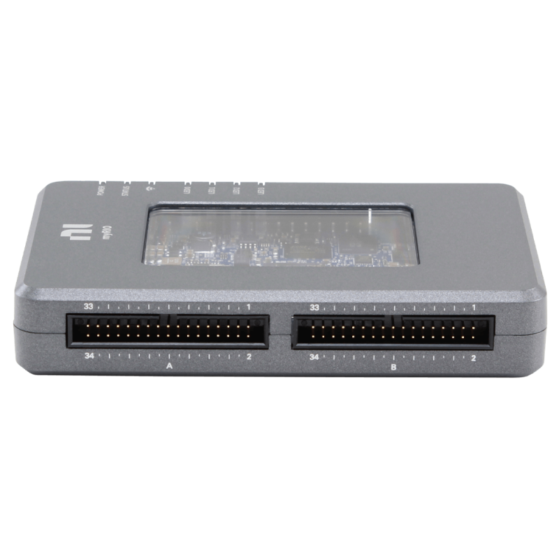
 Design with myRIO in Cirkit Designer
Introduction
The myRIO device is an advanced embedded hardware platform designed by National Instruments that integrates a real-time processor, a field-programmable gate array (FPGA), and a variety of input/output (I/O) options into a single compact unit. This powerful tool is commonly used in education and research for designing control systems, mechatronics, robotics, and other applications requiring real-time processing and flexible hardware interfacing.
Explore Projects Built with myRIO
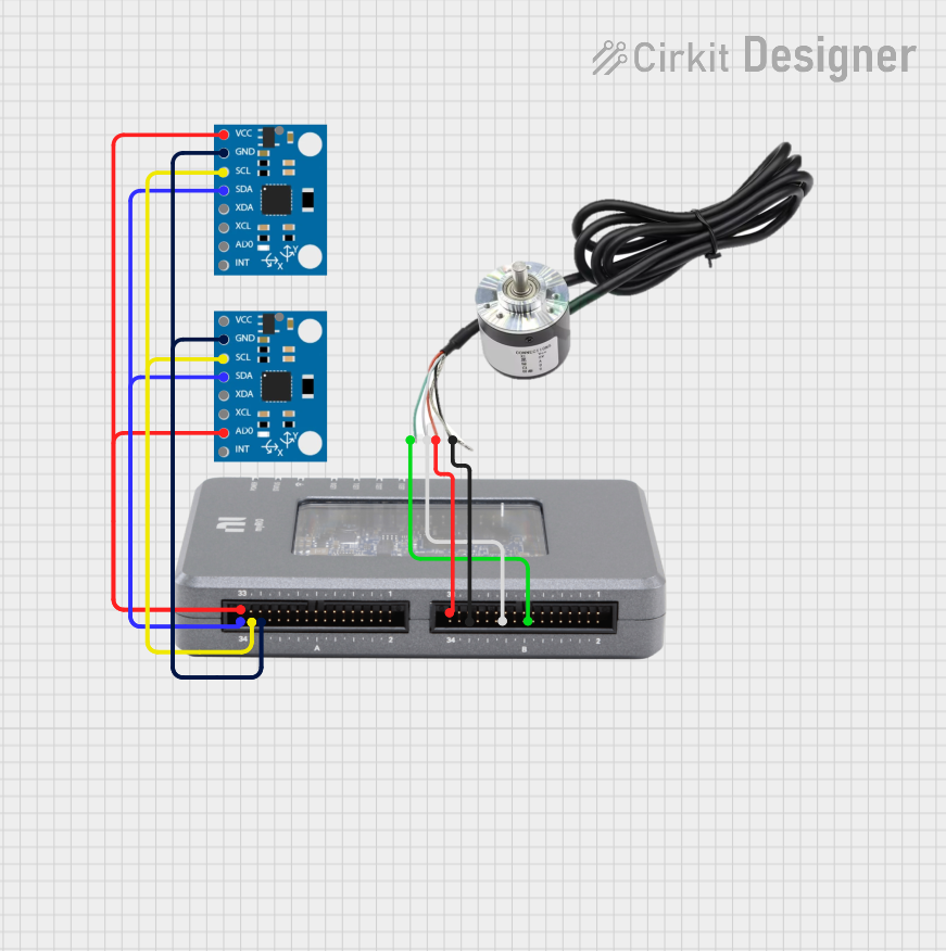
 Open Project in Cirkit Designer
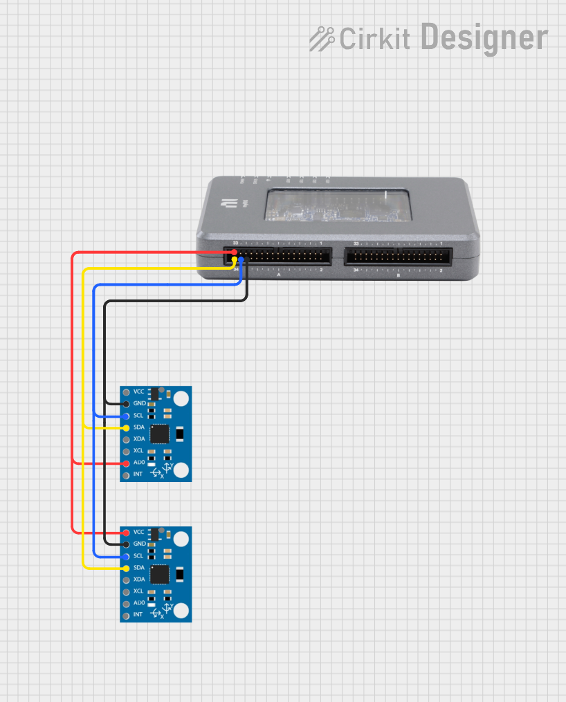
 Open Project in Cirkit Designer
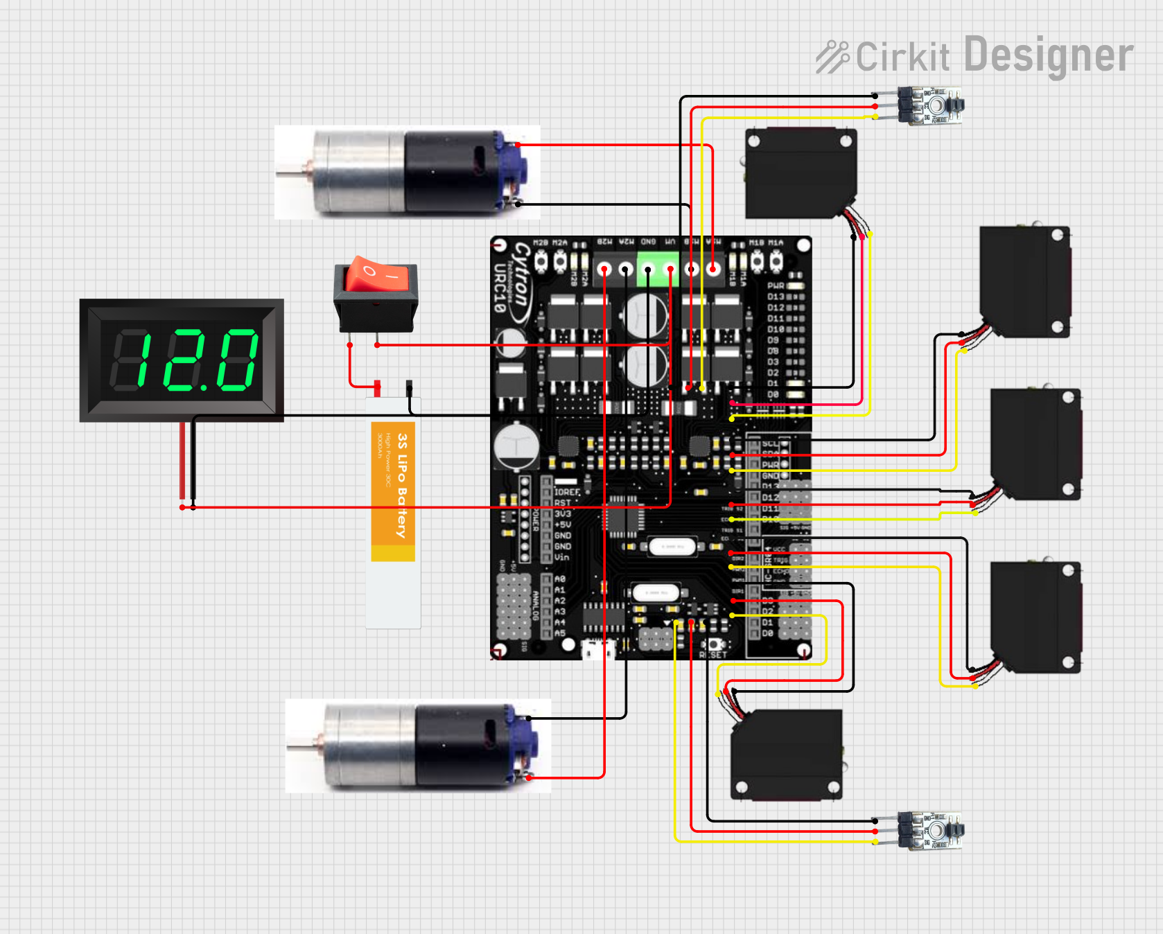
 Open Project in Cirkit Designer
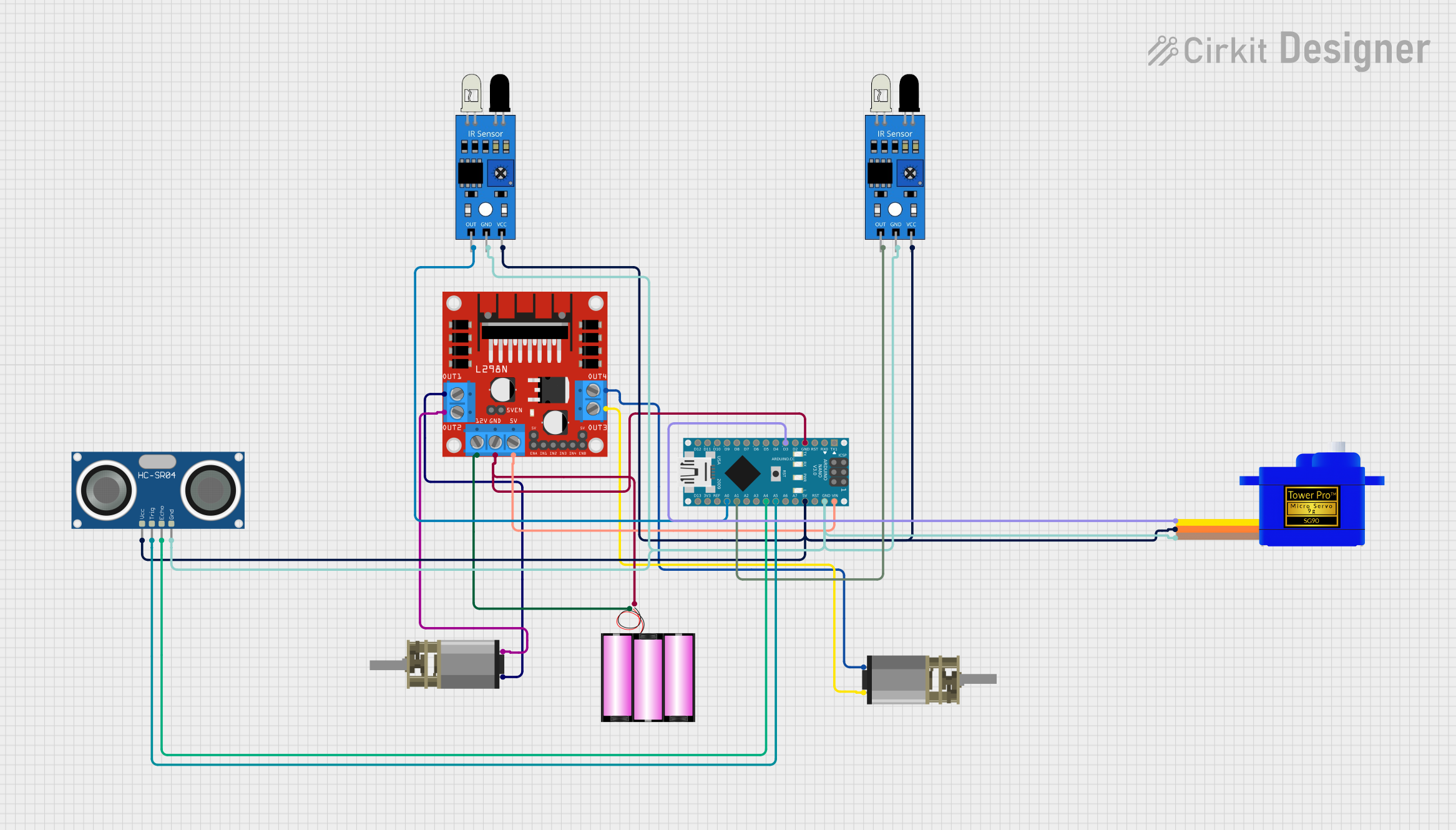
 Open Project in Cirkit Designer
Explore Projects Built with myRIO

 Open Project in Cirkit Designer
 Open Project in Cirkit Designer
 Open Project in Cirkit Designer
 Open Project in Cirkit Designer
Common Applications and Use Cases
- Robotics and automated systems
- Data acquisition and signal processing
- Rapid prototyping of control systems
- Teaching and research in engineering and science
- Custom embedded system development
Technical Specifications
Key Technical Details
- Processor: ARM Cortex-A9 dual-core CPU
- FPGA: Xilinx Zynq-7010
- Memory: 256 MB DDR3 RAM, 512 MB onboard storage
- Operating System: NI Linux Real-Time
- Power Ratings: 6V to 16V DC input
Pin Configuration and Descriptions
| Pin Number | Description | Voltage | Current |
|---|---|---|---|
| 1 | Analog Input 0 | 0-5 V | - |
| 2 | Analog Input 1 | 0-5 V | - |
| ... | ... | ... | ... |
| 10 | Digital I/O 0 | 0-3.3 V | 2-8 mA |
| 11 | Digital I/O 1 | 0-3.3 V | 2-8 mA |
| ... | ... | ... | ... |
| 20 | Ground | - | - |
| 21 | Power Supply Input | 6-16 V | - |
| ... | ... | ... | ... |
Note: This is a simplified representation. Refer to the myRIO User Manual for the complete pinout and specifications.
Usage Instructions
How to Use the Component in a Circuit
- Powering the Device: Connect a DC power supply within the specified voltage range to the power input pins.
- Connecting I/O: Attach sensors, actuators, or other peripherals to the appropriate analog or digital I/O pins.
- Programming the Device: Use NI LabVIEW software to develop programs for the real-time processor and the FPGA.
- Deploying the Application: Transfer the LabVIEW code to the myRIO device and run it to interact with the connected I/O.
Important Considerations and Best Practices
- Ensure that all connected peripherals are compatible with the voltage and current specifications of the myRIO I/O pins.
- Use proper anti-static precautions when handling the myRIO to prevent damage to the sensitive electronics.
- Regularly update the firmware and software tools to the latest versions for optimal performance and compatibility.
Troubleshooting and FAQs
Common Issues Users Might Face
- Power Issues: If the myRIO does not power on, check the power supply and connections.
- I/O Not Responding: Verify that the I/O pins are configured correctly in the LabVIEW project.
- Software Deployment Errors: Ensure that the myRIO and the computer are on the same network and that the correct device is selected in LabVIEW.
Solutions and Tips for Troubleshooting
- Power LED Not Lit: Confirm that the power supply is within the specified range and properly connected.
- Unresponsive I/O: Check for loose connections and review the LabVIEW code for proper I/O initialization.
- Deployment Issues: Disable firewalls or antivirus software that may be blocking communication between the computer and the myRIO.
FAQs
Q: Can I use the myRIO without LabVIEW? A: While LabVIEW is the primary development environment for myRIO, it is possible to use other tools and languages that support the ARM processor and FPGA.
Q: What is the maximum sampling rate for analog inputs? A: The maximum sampling rate depends on the configuration and number of channels used. Refer to the myRIO specifications for detailed information.
Q: How do I update the firmware on myRIO? A: Firmware updates can be performed using the NI MAX (Measurement & Automation Explorer) software.
For further assistance, consult the myRIO User Manual or contact National Instruments support.
Note: This documentation is a general guide and may not cover all aspects of the myRIO device. For comprehensive information, always refer to the official documentation provided by National Instruments.