How to Use Lolin32 ESP32: Examples, Pinouts, and Specs
Introduction
The Lolin32 ESP32, manufactured by WeMos, is a compact development board based on the powerful ESP32 microcontroller. It features integrated Wi-Fi and Bluetooth capabilities, making it an excellent choice for Internet of Things (IoT) projects, wireless communication, and rapid prototyping. Its small form factor and versatile functionality allow developers to create connected devices with ease.
Explore Projects Built with Lolin32 ESP32

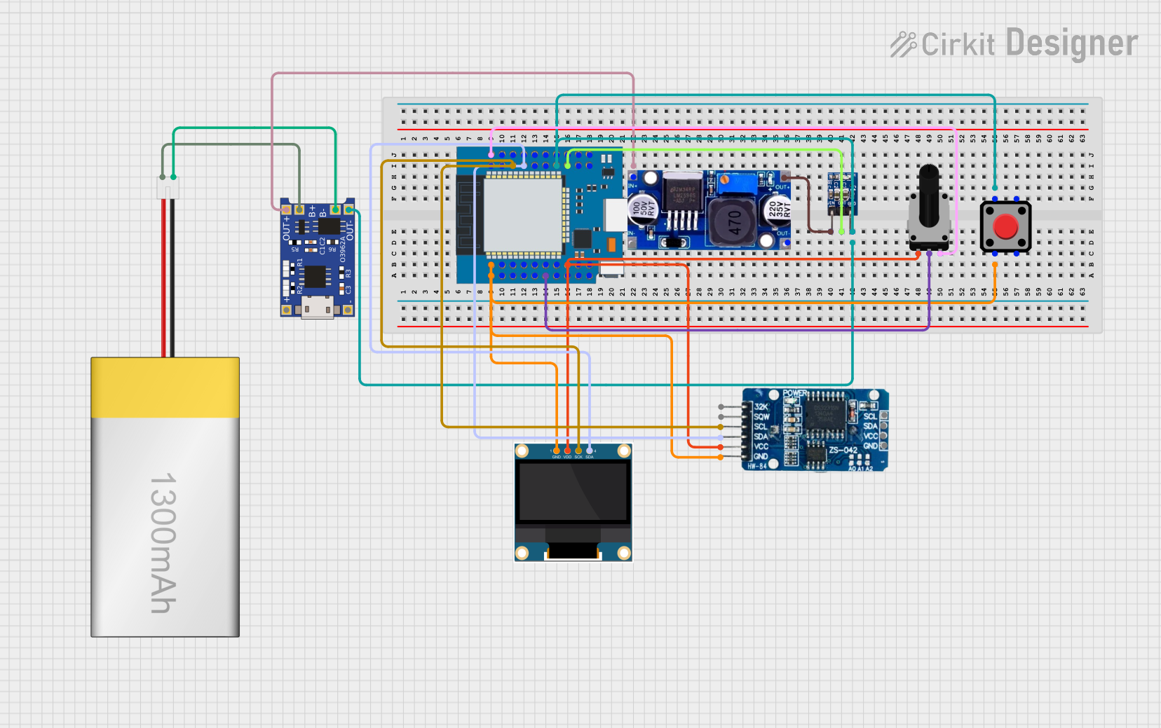
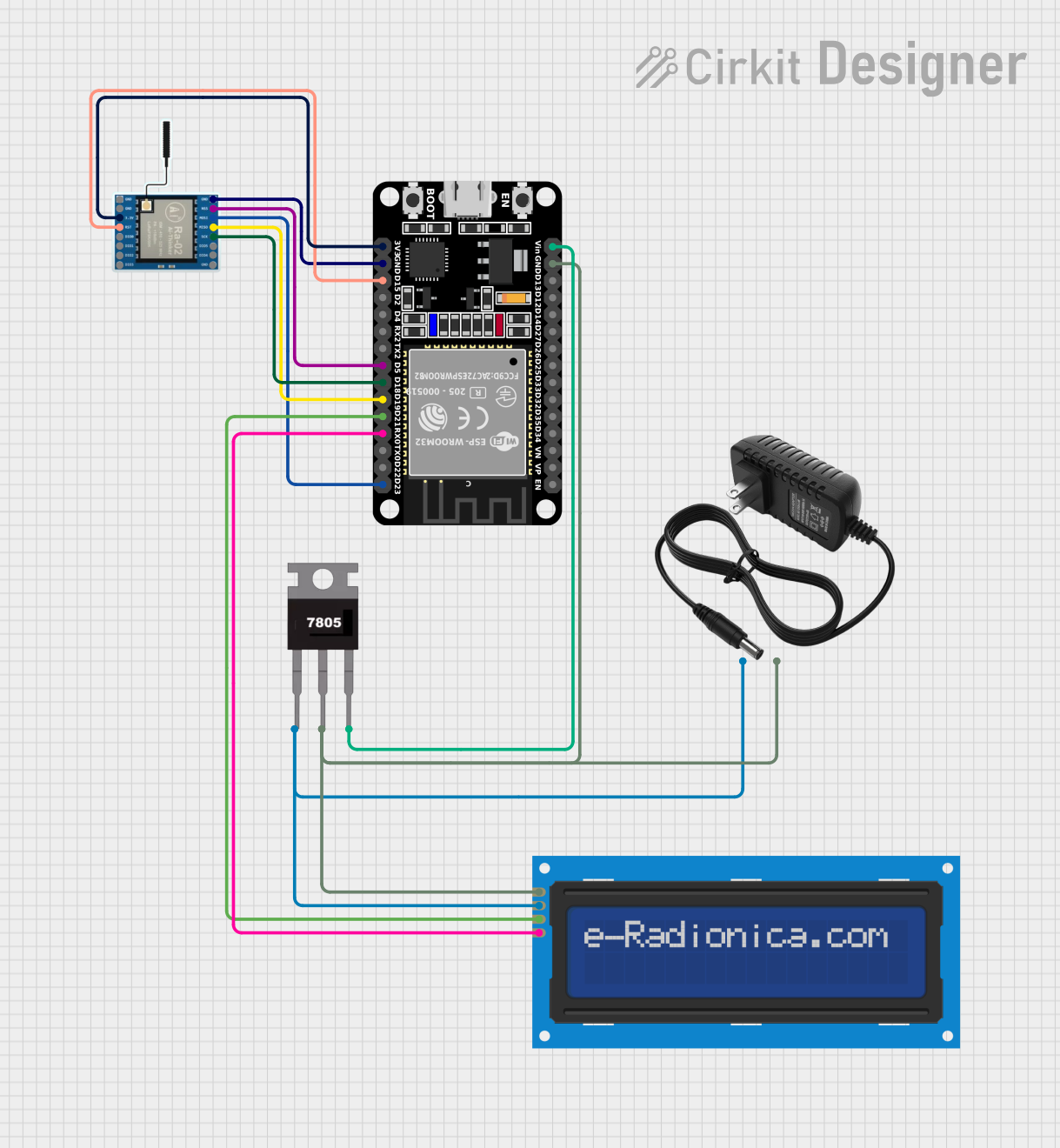
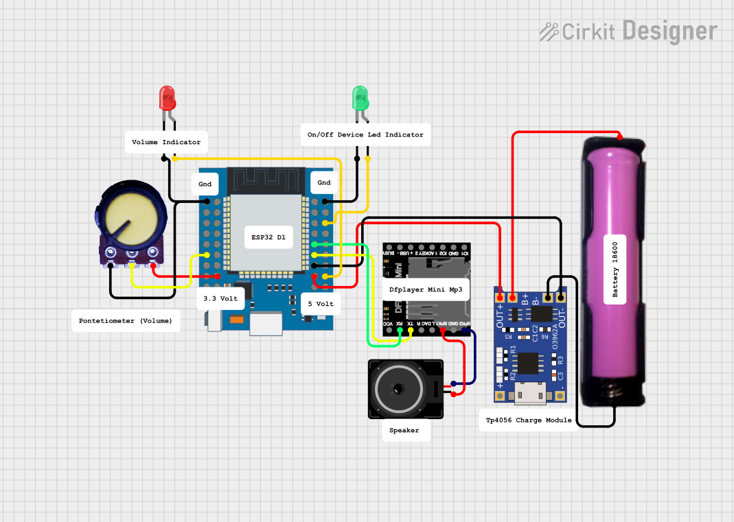
Explore Projects Built with Lolin32 ESP32
Common Applications and Use Cases
- IoT devices and smart home automation
- Wireless sensor networks
- Wearable technology
- Robotics and remote control systems
- Prototyping for Wi-Fi and Bluetooth-enabled applications
Technical Specifications
The Lolin32 ESP32 is designed to provide robust performance while maintaining a compact size. Below are its key technical specifications:
| Parameter | Specification |
|---|---|
| Microcontroller | ESP32 (dual-core, 32-bit Xtensa LX6) |
| Clock Speed | Up to 240 MHz |
| Flash Memory | 4 MB (SPI Flash) |
| SRAM | 520 KB |
| Wi-Fi | 802.11 b/g/n (2.4 GHz) |
| Bluetooth | Bluetooth 4.2 (Classic and BLE) |
| Operating Voltage | 3.3V |
| Input Voltage (VIN) | 5V (via USB or VIN pin) |
| GPIO Pins | 32 (multipurpose, including ADC, DAC, PWM, I2C, SPI) |
| ADC Resolution | 12-bit |
| DAC Resolution | 8-bit |
| USB Interface | Micro-USB (for programming and power) |
| Dimensions | 50 mm x 25.4 mm |
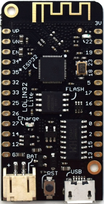
Pin Configuration and Descriptions
The Lolin32 ESP32 features a variety of pins for different functionalities. Below is the pinout description:
| Pin Name | Function | Description |
|---|---|---|
| VIN | Power Input | Accepts 5V input for powering the board. |
| 3V3 | 3.3V Output | Provides 3.3V output for external components. |
| GND | Ground | Common ground for the circuit. |
| EN | Enable | Enables or disables the ESP32 chip. |
| GPIO0 | General Purpose I/O | Used for boot mode selection or general I/O. |
| GPIO2 | General Purpose I/O | Can be used as an output or input pin. |
| GPIO12-19 | General Purpose I/O | Multipurpose pins for ADC, PWM, I2C, SPI, etc. |
| TXD0, RXD0 | UART0 (TX, RX) | Default UART for serial communication. |
| ADC1_0-ADC1_7 | Analog Input | 12-bit ADC channels for analog signal input. |
| DAC1, DAC2 | Digital-to-Analog Converter | 8-bit DAC output pins. |
| I2C (SDA, SCL) | I2C Communication | Pins for I2C communication (software-configurable). |
| SPI (MOSI, MISO, SCK, CS) | SPI Communication | Pins for SPI communication (software-configurable). |
Usage Instructions
The Lolin32 ESP32 is easy to use and can be programmed using the Arduino IDE or other development environments like PlatformIO. Below are the steps to get started:
1. Setting Up the Development Environment
- Download and install the Arduino IDE from arduino.cc.
- Open the Arduino IDE and go to File > Preferences.
- In the "Additional Board Manager URLs" field, add the following URL:
https://dl.espressif.com/dl/package_esp32_index.json - Go to Tools > Board > Boards Manager, search for "ESP32," and install the ESP32 board package.
2. Connecting the Lolin32 ESP32
- Connect the Lolin32 ESP32 to your computer using a micro-USB cable.
- Select the correct board and port in the Arduino IDE:
- Board: "ESP32 Dev Module"
- Port: Select the COM port corresponding to your device.
3. Example Code: Blinking an LED
The following example demonstrates how to blink an LED connected to GPIO2:
// Define the GPIO pin for the LED
const int ledPin = 2;

void setup() {
  // Set the LED pin as an output
  pinMode(ledPin, OUTPUT);
}

void loop() {
  // Turn the LED on
  digitalWrite(ledPin, HIGH);
  delay(1000); // Wait for 1 second

  // Turn the LED off
  digitalWrite(ledPin, LOW);
  delay(1000); // Wait for 1 second
}
Important Considerations and Best Practices
- Power Supply: Ensure the board is powered with a stable 5V supply via USB or VIN pin.
- GPIO Voltage Levels: The GPIO pins operate at 3.3V. Avoid applying 5V directly to the pins.
- Boot Mode: To enter bootloader mode, hold the "BOOT" button while pressing the "EN" button.
- External Components: Use appropriate resistors, capacitors, or level shifters when interfacing with external devices.
Troubleshooting and FAQs
Common Issues and Solutions
Problem: The board is not detected by the computer.
- Solution: Ensure the USB cable is functional and supports data transfer. Install the required USB-to-serial driver (e.g., CP210x or CH340).
Problem: Uploading code fails with a timeout error.
- Solution: Hold the "BOOT" button while uploading the code to enter bootloader mode.
Problem: Wi-Fi or Bluetooth is not working.
- Solution: Verify the code and ensure the correct SSID and password are used for Wi-Fi. For Bluetooth, ensure the device is discoverable and paired correctly.
Problem: GPIO pins are not functioning as expected.
- Solution: Check the pin configuration in your code and ensure no conflicting peripherals are using the same pins.
FAQs
Q: Can I power the Lolin32 ESP32 with a battery?
- A: Yes, you can power the board using a 3.7V LiPo battery connected to the JST connector (if available) or via the VIN pin.
Q: What is the maximum current output of the 3.3V pin?
- A: The 3.3V pin can supply up to 500 mA, depending on the input power source.
Q: Can I use the Lolin32 ESP32 with MicroPython?
- A: Yes, the ESP32 is compatible with MicroPython. You can flash the MicroPython firmware to the board and use it for development.
By following this documentation, you can effectively utilize the Lolin32 ESP32 for your projects and troubleshoot common issues with ease.