Cirkit Designer
Your all-in-one circuit design IDE
Home /
Component Documentation
How to Use GSM MODULE SIM900A: Examples, Pinouts, and Specs
Introduction
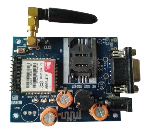
The GSM Module SIM900A is a versatile and widely-used component that enables devices to communicate over a mobile network. It supports sending and receiving SMS, voice, and data, making it an essential component for various IoT (Internet of Things) applications. This module is particularly popular for projects that require remote monitoring, control, and data logging.
Explore Projects Built with GSM MODULE SIM900A
Arduino UNO and SIM900A GSM Module Communication System
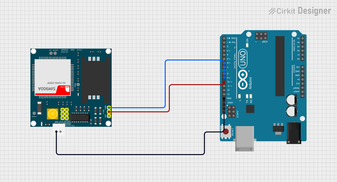
This circuit interfaces an Arduino UNO with a SIM900A GSM module. The Arduino communicates with the SIM900A via digital pins D9 and D10 for serial data transmission and reception, while both devices share a common ground.
Arduino UNO and SIM900A GSM Module for Remote Communication
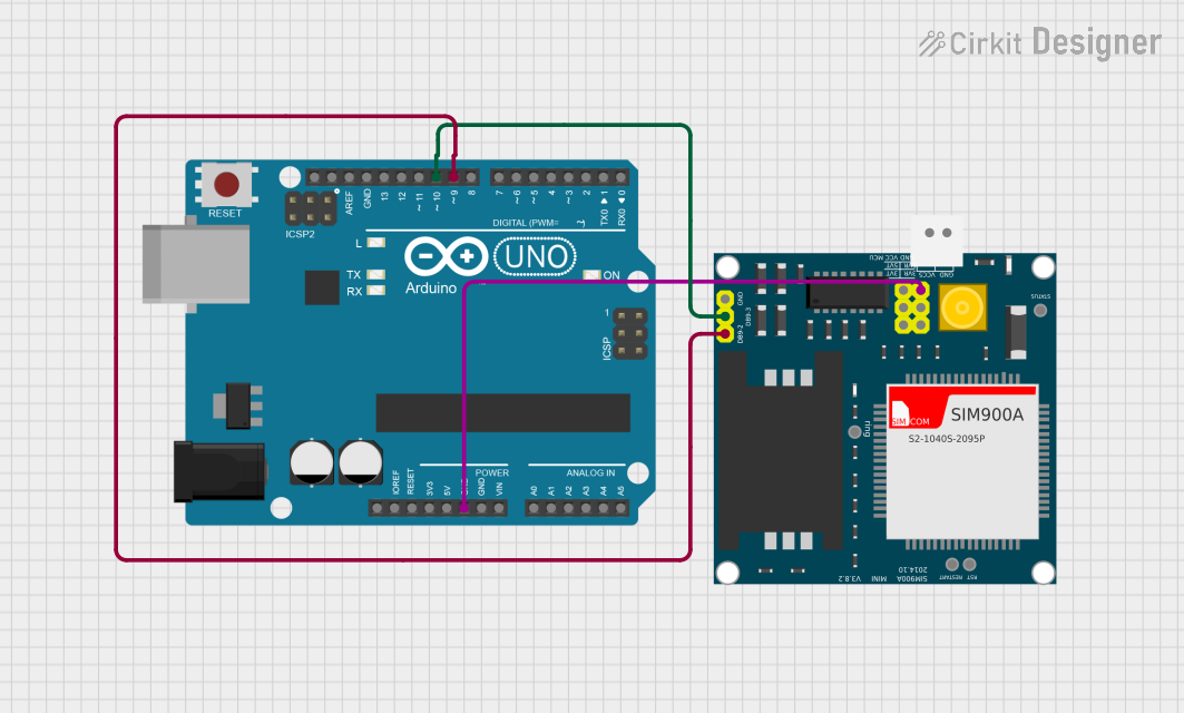
This circuit interfaces an Arduino UNO with a SIM900A GSM module. The Arduino controls the SIM900A via digital pins D9 and D10 for serial communication, while both components share a common ground.
Arduino UNO and SIM900A GSM Module for Remote Communication
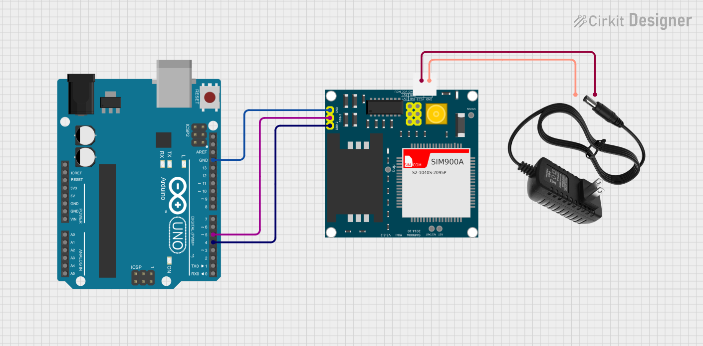
This circuit integrates an Arduino UNO with a SIM900A GSM module, powered by a 12V power supply. The Arduino communicates with the SIM900A via digital pins D4 and D5 for TX and RX respectively, enabling GSM communication capabilities.
Arduino UNO and SIM900A GSM Module Interface
This circuit connects an Arduino UNO microcontroller with a SIM900A GSM/GPRS module, enabling cellular communication capabilities. The Arduino's digital pins D7 and D8 are connected to the SIM900A's 5VT and 5VR pins, likely for serial communication. A separate 5V connector provides power to the SIM900A, with common ground connections established between all components.
Explore Projects Built with GSM MODULE SIM900A
Arduino UNO and SIM900A GSM Module Communication System
This circuit interfaces an Arduino UNO with a SIM900A GSM module. The Arduino communicates with the SIM900A via digital pins D9 and D10 for serial data transmission and reception, while both devices share a common ground.
Arduino UNO and SIM900A GSM Module for Remote Communication
This circuit interfaces an Arduino UNO with a SIM900A GSM module. The Arduino controls the SIM900A via digital pins D9 and D10 for serial communication, while both components share a common ground.
Arduino UNO and SIM900A GSM Module for Remote Communication
This circuit integrates an Arduino UNO with a SIM900A GSM module, powered by a 12V power supply. The Arduino communicates with the SIM900A via digital pins D4 and D5 for TX and RX respectively, enabling GSM communication capabilities.
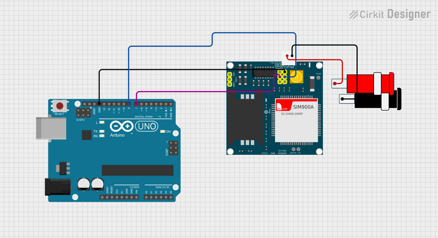
Arduino UNO and SIM900A GSM Module Interface
This circuit connects an Arduino UNO microcontroller with a SIM900A GSM/GPRS module, enabling cellular communication capabilities. The Arduino's digital pins D7 and D8 are connected to the SIM900A's 5VT and 5VR pins, likely for serial communication. A separate 5V connector provides power to the SIM900A, with common ground connections established between all components.
Common Applications and Use Cases
- Remote Monitoring: Collecting data from sensors and sending it to a remote server.
- Home Automation: Controlling home appliances via SMS or mobile app.
- Security Systems: Sending alerts and notifications in case of security breaches.
- Vehicle Tracking: Sending GPS coordinates and other data for fleet management.
- Industrial Automation: Monitoring and controlling industrial processes remotely.
Technical Specifications
Key Technical Details
| Parameter | Value |
|---|---|
| Operating Voltage | 3.2V - 4.8V |
| Operating Current | 1.5A (peak), 20mA (idle) |
| Frequency Bands | GSM 900/1800 MHz |
| Data Rate | Up to 85.6 kbps (GPRS) |
| SMS Support | Text and PDU mode |
| Voice Support | Full-duplex, Echo cancellation |
| Interface | UART, AT Commands |
Pin Configuration and Descriptions
| Pin Number | Pin Name | Description |
|---|---|---|
| 1 | VCC | Power supply (3.2V - 4.8V) |
| 2 | GND | Ground |
| 3 | TXD | Transmit data (UART) |
| 4 | RXD | Receive data (UART) |
| 5 | DTR | Data Terminal Ready (for sleep mode control) |
| 6 | RST | Reset (active low) |
| 7 | MIC+ | Microphone input positive |
| 8 | MIC- | Microphone input negative |
| 9 | SPK+ | Speaker output positive |
| 10 | SPK- | Speaker output negative |
Usage Instructions
How to Use the Component in a Circuit
- Power Supply: Connect the VCC pin to a 3.2V - 4.8V power source and the GND pin to the ground.
- UART Communication: Connect the TXD pin to the RX pin of the microcontroller (e.g., Arduino UNO) and the RXD pin to the TX pin of the microcontroller.
- Antenna: Attach an external antenna to the module for better signal reception.
- SIM Card: Insert a valid SIM card into the SIM card slot on the module.
- Microphone and Speaker: Connect a microphone to the MIC+ and MIC- pins and a speaker to the SPK+ and SPK- pins if voice communication is required.
Important Considerations and Best Practices
- Power Supply: Ensure a stable power supply to avoid unexpected resets or malfunctions.
- Antenna Placement: Place the antenna in a location with good signal strength to ensure reliable communication.
- UART Baud Rate: Configure the UART baud rate to match the module's default setting (usually 9600 bps).
- AT Commands: Familiarize yourself with the AT commands used to control the module. Refer to the SIM900A AT Command Manual for detailed information.
Example Code for Arduino UNO
#include <SoftwareSerial.h>

// Create a software serial object for communication with the GSM module
SoftwareSerial gsm(7, 8); // RX, TX

void setup() {
  // Initialize serial communication with the computer
  Serial.begin(9600);
  // Initialize serial communication with the GSM module
  gsm.begin(9600);
  // Wait for the GSM module to initialize
  delay(1000);
  // Send an AT command to check if the module is responding
  gsm.println("AT");
  // Wait for a response
  delay(1000);
  // Read and print the response from the GSM module
  while (gsm.available()) {
    Serial.write(gsm.read());
  }
}

void loop() {
  // Check if there is any data from the GSM module
  if (gsm.available()) {
    // Read and print the data from the GSM module
    Serial.write(gsm.read());
  }
  // Check if there is any data from the computer
  if (Serial.available()) {
    // Read and send the data to the GSM module
    gsm.write(Serial.read());
  }
}
Troubleshooting and FAQs
Common Issues Users Might Face
No Response from the Module:
- Solution: Check the power supply and ensure it is within the specified range. Verify the connections, especially the UART pins.
Poor Signal Reception:
- Solution: Ensure the antenna is properly connected and placed in an area with good signal strength. Try using a different SIM card or network provider.
Unable to Send/Receive SMS:
- Solution: Verify that the SIM card has sufficient balance and is not locked. Check the AT command syntax and ensure the module is registered on the network.
Module Resets Frequently:
- Solution: Ensure a stable power supply with sufficient current capacity. Avoid using long or thin wires for power connections.
Solutions and Tips for Troubleshooting
- Check Connections: Ensure all connections are secure and correctly wired.
- Use a Stable Power Supply: A regulated power supply can prevent unexpected resets and malfunctions.
- Refer to AT Command Manual: The SIM900A AT Command Manual provides detailed information on using the module effectively.
- Monitor Serial Communication: Use serial monitoring tools to debug and understand the communication between the microcontroller and the GSM module.
By following this documentation, users can effectively integrate the GSM Module SIM900A into their projects, ensuring reliable and efficient communication over mobile networks.