
How to Use PTC Heater: Examples, Pinouts, and Specs
 Design with PTC Heater in Cirkit Designer
Introduction
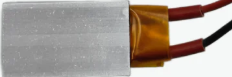
A Positive Temperature Coefficient (PTC) heater is a type of heating element that increases its electrical resistance as its temperature rises. This self-regulating property ensures that the heater maintains a consistent temperature without the need for external control circuits, making it highly efficient and safe. PTC heaters are widely used in applications such as space heaters, automotive cabin heating, dehumidifiers, and battery warmers. Their durability, energy efficiency, and safety make them a popular choice for both industrial and consumer applications.
Explore Projects Built with PTC Heater
 Open Project in Cirkit Designer
 Open Project in Cirkit Designer
 Open Project in Cirkit Designer
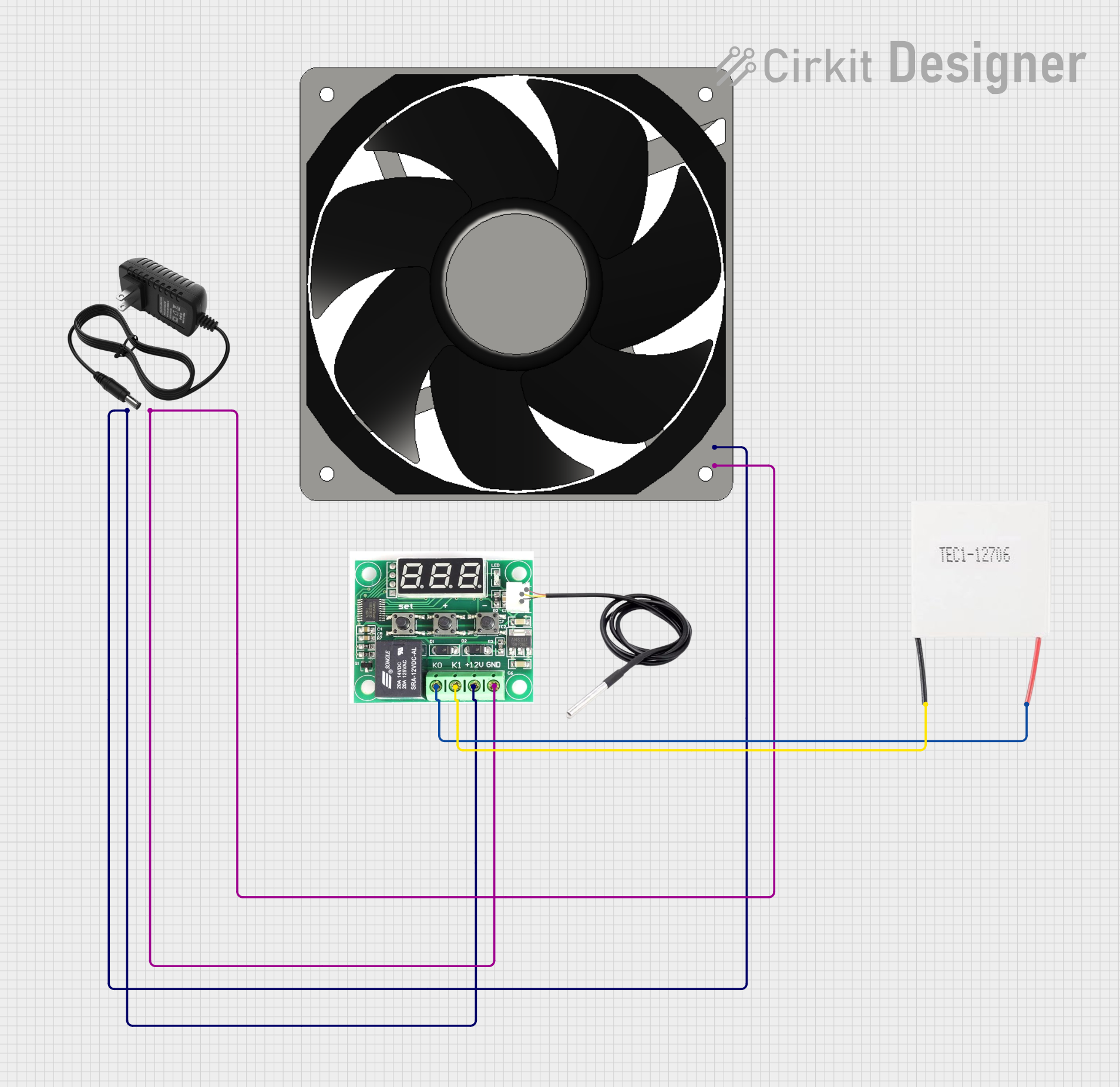 Open Project in Cirkit Designer
Explore Projects Built with PTC Heater
Open Project in Cirkit DesignerOpen Project in Cirkit DesignerOpen Project in Cirkit DesignerOpen Project in Cirkit DesignerTechnical Specifications
Below are the general technical specifications for a typical PTC heater. Note that specific values may vary depending on the manufacturer and model.
Key Specifications
- Operating Voltage: 12V, 24V, or 220V (depending on the model)
- Power Rating: 10W to 500W
- Temperature Range: 50°C to 300°C (self-regulating)
- Material: Ceramic heating element with aluminum casing
- Resistance Characteristics: Increases with temperature
- Safety Features: Overheat protection (self-regulating)
Pin Configuration and Descriptions
PTC heaters typically have two terminals for electrical connections. Below is a table describing the pin configuration:
| Pin Number | Label | Description |
|---|---|---|
| 1 | Positive (+) | Connect to the positive terminal of the power supply. |
| 2 | Negative (-) | Connect to the negative terminal (ground). |
Usage Instructions
How to Use the PTC Heater in a Circuit
- Power Supply: Ensure the PTC heater is connected to a power supply that matches its rated voltage (e.g., 12V or 24V). Using an incorrect voltage can damage the heater or reduce its efficiency.
- Wiring: Connect the positive terminal of the power supply to the positive pin of the PTC heater and the negative terminal to the negative pin.
- Mounting: Secure the PTC heater in a location where it can safely dissipate heat. Avoid placing it near flammable materials.
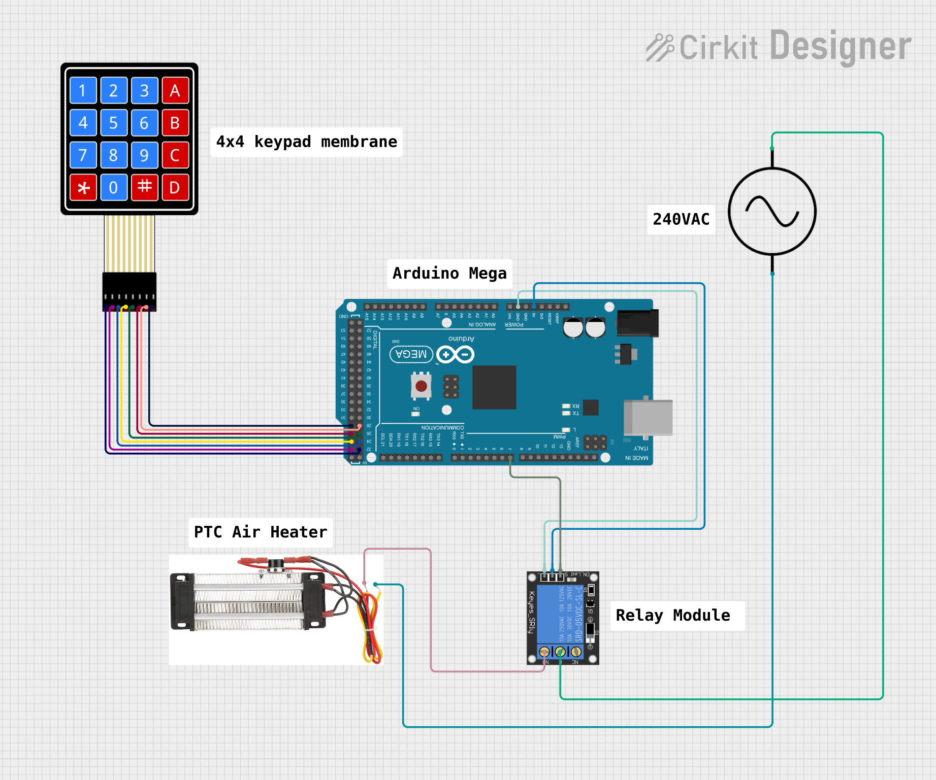
- Control: While the PTC heater is self-regulating, you can use a relay or MOSFET to control its operation via a microcontroller like an Arduino.
Important Considerations and Best Practices
- Ventilation: Ensure proper airflow around the PTC heater to prevent overheating of surrounding components.
- Current Rating: Verify that the power supply can provide sufficient current for the heater's power rating.
- Insulation: Use heat-resistant wires and connectors to avoid damage from high temperatures.
- Safety: Avoid touching the heater during operation, as it can reach high temperatures.
Example: Using a PTC Heater with an Arduino UNO
Below is an example of how to control a 12V PTC heater using an Arduino UNO and a relay module.
// Example code to control a PTC heater using an Arduino UNO and a relay module

const int relayPin = 7; // Pin connected to the relay module

void setup() {
  pinMode(relayPin, OUTPUT); // Set the relay pin as an output
  digitalWrite(relayPin, LOW); // Ensure the relay is off at startup
}

void loop() {
  // Turn the PTC heater on for 10 seconds
  digitalWrite(relayPin, HIGH); // Activate the relay (heater ON)
  delay(10000); // Wait for 10 seconds

  // Turn the PTC heater off for 10 seconds
  digitalWrite(relayPin, LOW); // Deactivate the relay (heater OFF)
  delay(10000); // Wait for 10 seconds
}
Note: Ensure the relay module is rated for the current and voltage of the PTC heater. Use an external power supply for the heater, as the Arduino cannot directly power it.
Troubleshooting and FAQs
Common Issues and Solutions
PTC Heater Not Heating:
- Cause: Incorrect voltage or insufficient current from the power supply.
- Solution: Verify that the power supply matches the heater's voltage and current requirements.
Overheating of Surrounding Components:
- Cause: Poor ventilation or improper mounting.
- Solution: Ensure adequate airflow and mount the heater away from sensitive components.
Heater Turns Off Too Quickly:
- Cause: The self-regulating feature may activate if the ambient temperature is too high.
- Solution: Use the heater in an environment where the ambient temperature is within its operating range.
Burnt Smell or Smoke:
- Cause: Overvoltage or damaged insulation.
- Solution: Disconnect the power immediately and inspect the wiring and heater for damage.
FAQs
Q: Can I use a PTC heater with a battery?
- A: Yes, as long as the battery voltage matches the heater's rated voltage and the battery can supply sufficient current.
Q: Does the PTC heater require a thermostat?
- A: No, the PTC heater is self-regulating and does not require an external thermostat.
Q: Can I control the temperature of the PTC heater?
- A: The temperature is self-regulated, but you can control the on/off cycles using a microcontroller or timer.
Q: Is the PTC heater safe for continuous operation?
- A: Yes, PTC heaters are designed for continuous operation, provided they are used within their specified voltage and current ratings.