How to Use INMP441 mic: Examples, Pinouts, and Specs
Introduction
The INMP441 is a high-performance, low-power digital MEMS (Micro-Electro-Mechanical Systems) microphone designed for high-quality audio capture. It features an I2S (Inter-IC Sound) interface, which allows direct digital audio output, eliminating the need for an external ADC (Analog-to-Digital Converter). This makes it an ideal choice for applications requiring compact design and efficient audio processing.
Explore Projects Built with INMP441 mic
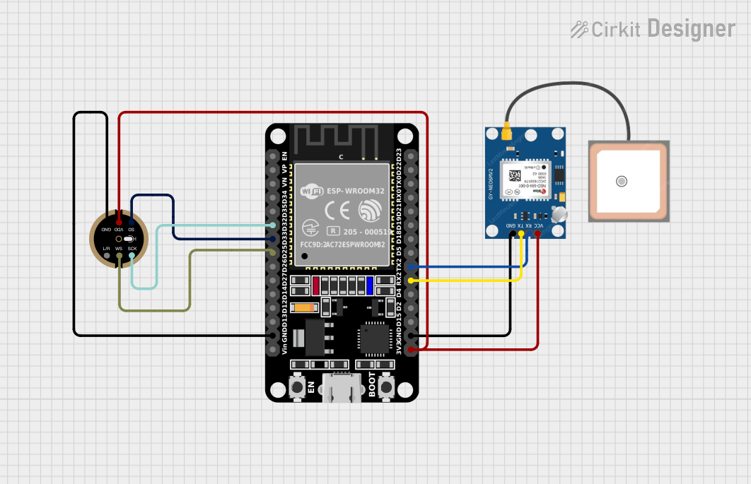
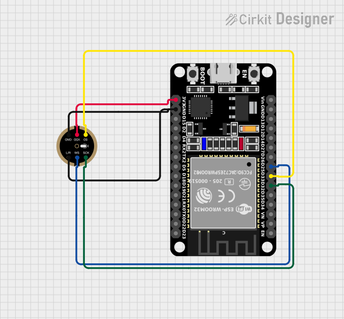
Explore Projects Built with INMP441 mic
Common Applications and Use Cases
- Smartphones and tablets
- Smart home devices (e.g., voice assistants, IoT devices)
- Audio recording systems
- Wearable devices
- Noise-canceling systems
- Portable audio equipment
Technical Specifications
The INMP441 microphone is designed to deliver excellent audio performance while maintaining low power consumption. Below are its key technical specifications:
| Parameter | Value |
|---|---|
| Supply Voltage (VDD) | 1.8V to 3.3V |
| Current Consumption | 1.4 mA (typical) |
| Signal-to-Noise Ratio (SNR) | 61 dB |
| Acoustic Overload Point | 120 dB SPL |
| Frequency Response | 60 Hz to 15 kHz |
| Output Format | I2S (Inter-IC Sound) |
| Sensitivity | -26 dBFS ±1 dB |
| Operating Temperature | -40°C to +85°C |
| Dimensions | 3.5 mm × 2.65 mm × 0.98 mm |
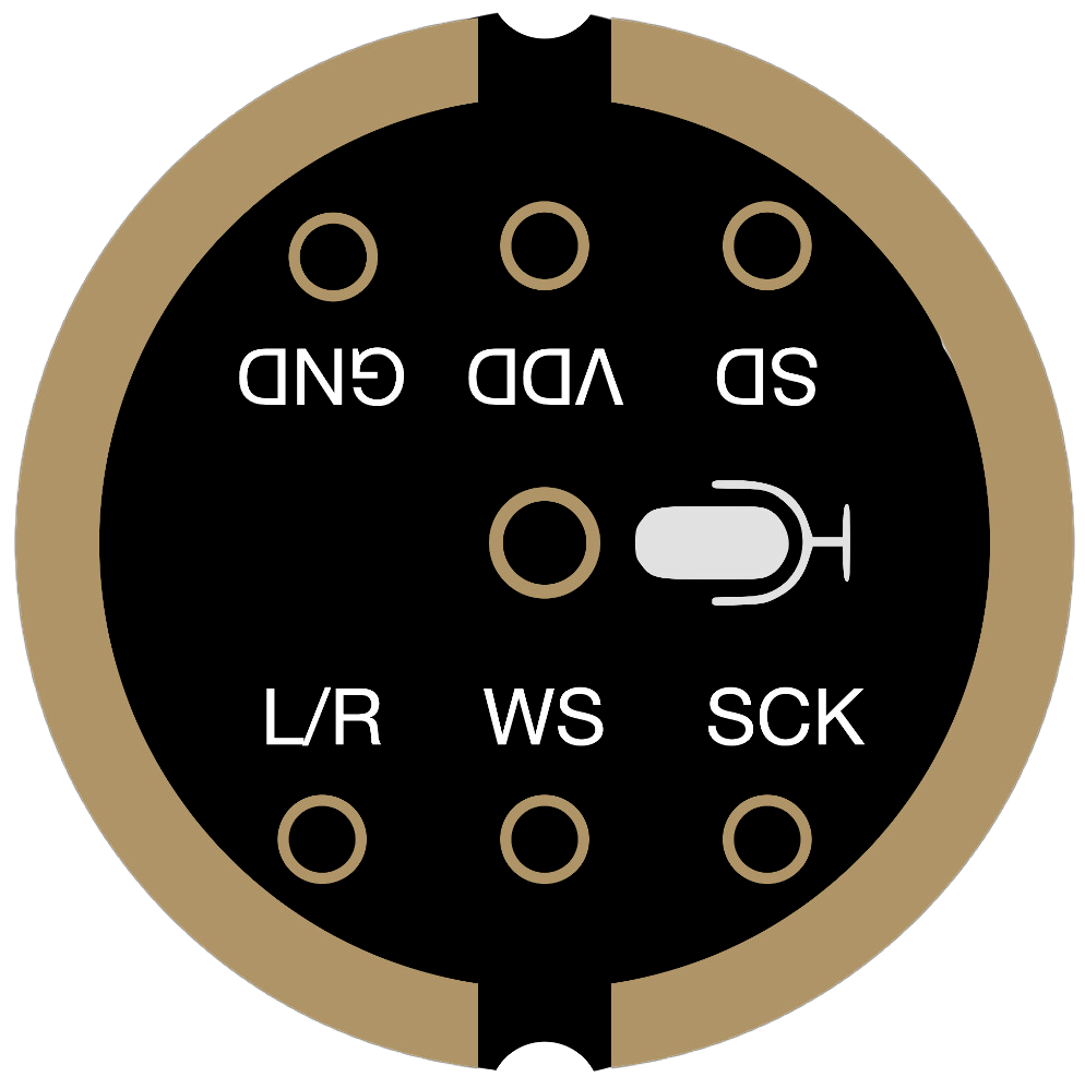
Pin Configuration and Descriptions
The INMP441 has a total of 7 pins. Below is the pinout and description:
| Pin Name | Pin Number | Description |
|---|---|---|
| VDD | 1 | Power supply input (1.8V to 3.3V). |
| GND | 2 | Ground connection. |
| WS | 3 | Word Select (I2S left/right channel selection). |
| SCK | 4 | Serial Clock (I2S clock input). |
| SD | 5 | Serial Data (I2S digital audio output). |
| L/R | 6 | Left/Right channel selection (connect to GND for left, VDD for right). |
| NC | 7 | No connection (leave unconnected). |
Usage Instructions
How to Use the INMP441 in a Circuit
- Power Supply: Connect the VDD pin to a 1.8V to 3.3V power source and the GND pin to ground.
- I2S Interface:
- Connect the
SCKpin to the I2S clock line of your microcontroller or audio processor. - Connect the
WSpin to the I2S word select line. - Connect the
SDpin to the I2S data input line of your microcontroller.
- Connect the
- Channel Selection: Use the
L/Rpin to configure the microphone as a left or right channel:- Connect to GND for left channel.
- Connect to VDD for right channel.
- Unused Pin: Leave the
NCpin unconnected.
Important Considerations and Best Practices
- Power Supply Decoupling: Place a 0.1 µF ceramic capacitor close to the VDD pin to reduce noise.
- I2S Configuration: Ensure your microcontroller or audio processor is configured to match the INMP441's I2S format (standard I2S, 24-bit data, MSB first).
- Microphone Placement: Position the microphone away from noisy components to minimize interference.
- PCB Design: Use a ground plane and keep traces for the I2S signals as short as possible to reduce noise and signal degradation.
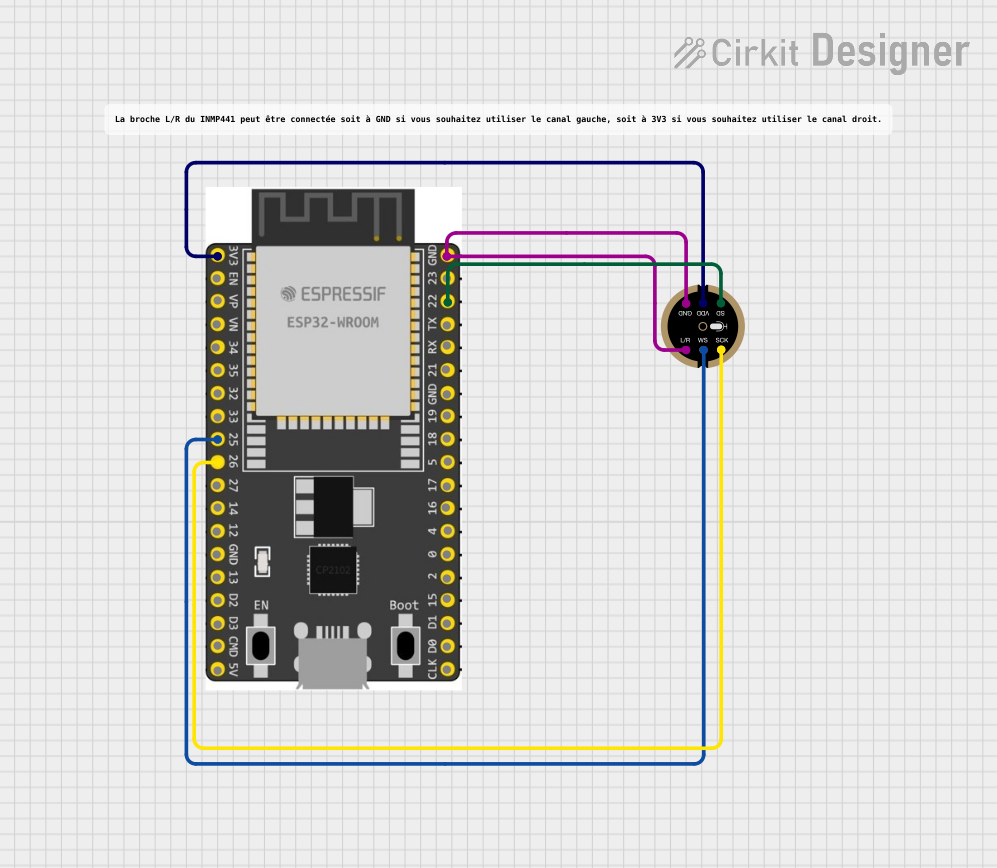
Example: Connecting INMP441 to Arduino UNO
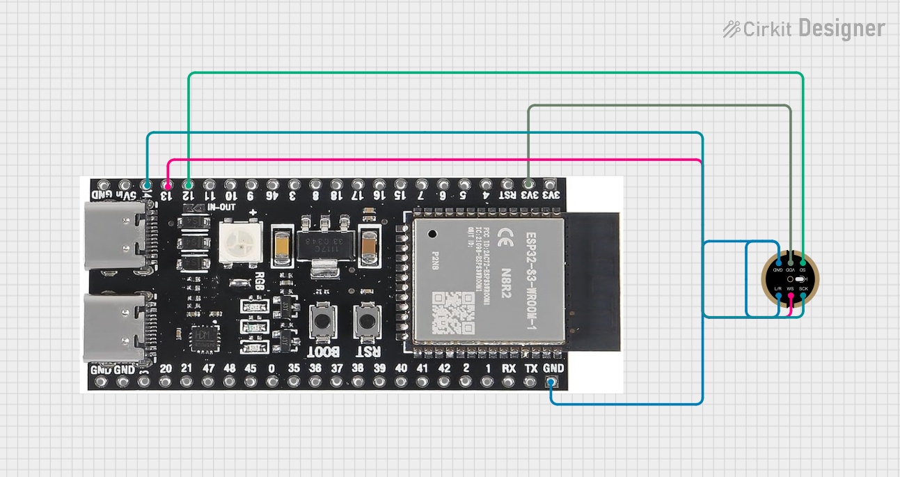
The Arduino UNO does not natively support I2S, but you can use an external I2S interface module or a microcontroller like the ESP32, which has built-in I2S support. Below is an example of how to use the INMP441 with an ESP32:
Wiring Diagram
| INMP441 Pin | ESP32 Pin |
|---|---|
| VDD | 3.3V |
| GND | GND |
| WS | GPIO25 |
| SCK | GPIO26 |
| SD | GPIO27 |
| L/R | GND (Left) |
Example Code
#include <driver/i2s.h>

// I2S configuration
#define I2S_NUM         I2S_NUM_0  // Use I2S port 0
#define I2S_WS          25         // Word Select pin
#define I2S_SCK         26         // Serial Clock pin
#define I2S_SD          27         // Serial Data pin

void setup() {
  // Configure I2S
  i2s_config_t i2s_config = {
    .mode = (i2s_mode_t)(I2S_MODE_MASTER | I2S_MODE_RX), // Master receive mode
    .sample_rate = 16000,                               // Sampling rate
    .bits_per_sample = I2S_BITS_PER_SAMPLE_16BIT,       // 16-bit audio
    .channel_format = I2S_CHANNEL_FMT_ONLY_LEFT,        // Left channel only
    .communication_format = I2S_COMM_FORMAT_I2S,       // Standard I2S format
    .intr_alloc_flags = 0,                             // Default interrupt allocation
    .dma_buf_count = 8,                                // Number of DMA buffers
    .dma_buf_len = 64                                  // Length of each DMA buffer
  };

  // Configure I2S pins
  i2s_pin_config_t pin_config = {
    .bck_io_num = I2S_SCK,  // Serial Clock
    .ws_io_num = I2S_WS,    // Word Select
    .data_out_num = -1,     // Not used (output)
    .data_in_num = I2S_SD   // Serial Data (input)
  };

  // Install and start I2S driver
  i2s_driver_install(I2S_NUM, &i2s_config, 0, NULL);
  i2s_set_pin(I2S_NUM, &pin_config);
}

void loop() {
  // Buffer to store audio data
  uint8_t audio_data[128];
  size_t bytes_read;

  // Read audio data from I2S
  i2s_read(I2S_NUM, audio_data, sizeof(audio_data), &bytes_read, portMAX_DELAY);

  // Process audio data (e.g., send to a server or save to storage)
}
Troubleshooting and FAQs
Common Issues and Solutions
No Audio Output:
- Ensure the I2S pins are correctly connected to the microcontroller.
- Verify that the microcontroller's I2S configuration matches the INMP441's specifications.
Distorted Audio:
- Check the power supply for noise or instability.
- Ensure the sampling rate and bit depth are correctly configured.
Microphone Not Detected:
- Verify the
L/Rpin configuration (GND for left, VDD for right). - Check for loose or incorrect connections.
- Verify the
High Noise Levels:
- Place the microphone away from noisy components.
- Use proper decoupling capacitors near the VDD pin.
FAQs
Q: Can the INMP441 be used with 5V logic?
A: No, the INMP441 operates at 1.8V to 3.3V. Use a level shifter if interfacing with 5V logic.
Q: Does the INMP441 support stereo audio?
A: Yes, you can use two INMP441 microphones, configuring one as the left channel (L/R pin to GND) and the other as the right channel (L/R pin to VDD).
Q: What is the maximum sampling rate supported?
A: The INMP441 supports sampling rates up to 48 kHz.