Cirkit Designer
Your all-in-one circuit design IDE
Home /
Component Documentation
How to Use Dual Digital Pot V1.0: Examples, Pinouts, and Specs
Introduction
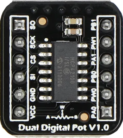
The Dual Digital Pot V1.0 (Manufacturer Part ID: DFR-10838) by DFRobot is a versatile electronic component designed to provide precise control over resistance values. This dual digital potentiometer is ideal for applications that require variable resistance adjustments, such as audio volume control, sensor calibration, and adjustable power supplies.
Explore Projects Built with Dual Digital Pot V1.0
Adafruit Circuit Playground-Based Interactive Control System with Pushbutton and Slide Potentiometers
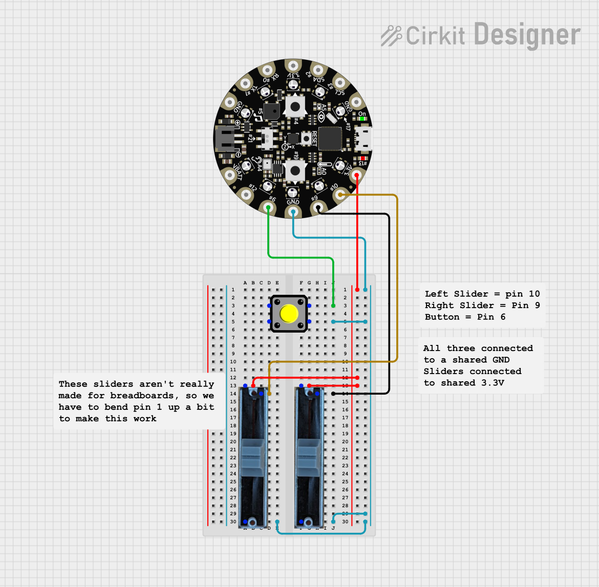
This circuit features an Adafruit Circuit Playground Dev Edition microcontroller interfaced with a pushbutton and two slide potentiometers. The pushbutton is connected to digital pin D6, while the potentiometers provide analog input to pins D9 and D10, allowing for variable control inputs.
Analog Multiplexer-Based Multi-Potentiometer Control System
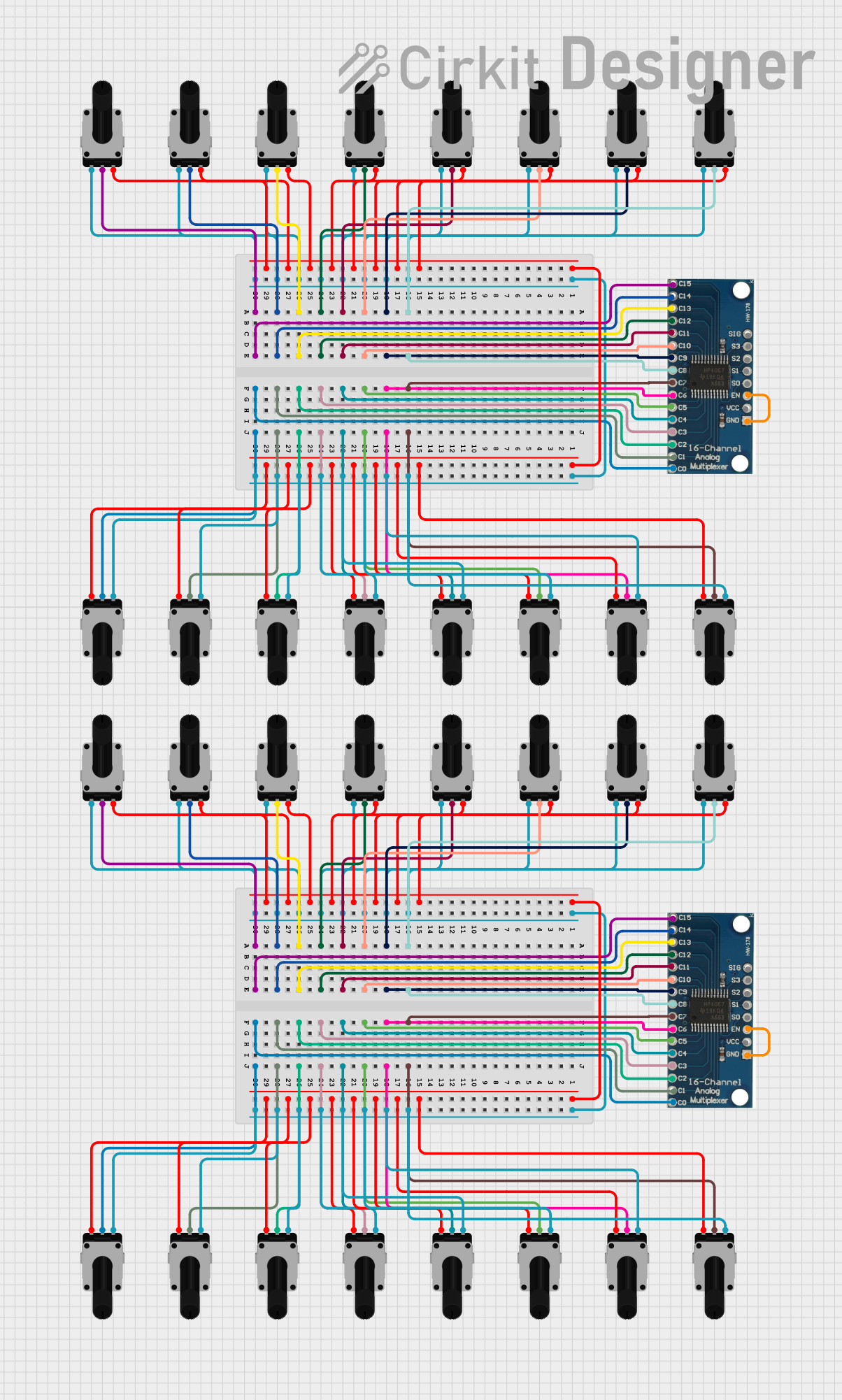
This circuit consists of two 16-channel analog multiplexers, each connected to 16 rotary potentiometers. The potentiometers' wiper terminals are connected to the multiplexer channels, allowing the multiplexers to select and output the analog voltage from any of the potentiometers.
Arduino Nano-Based Multi-Channel Volume Controller
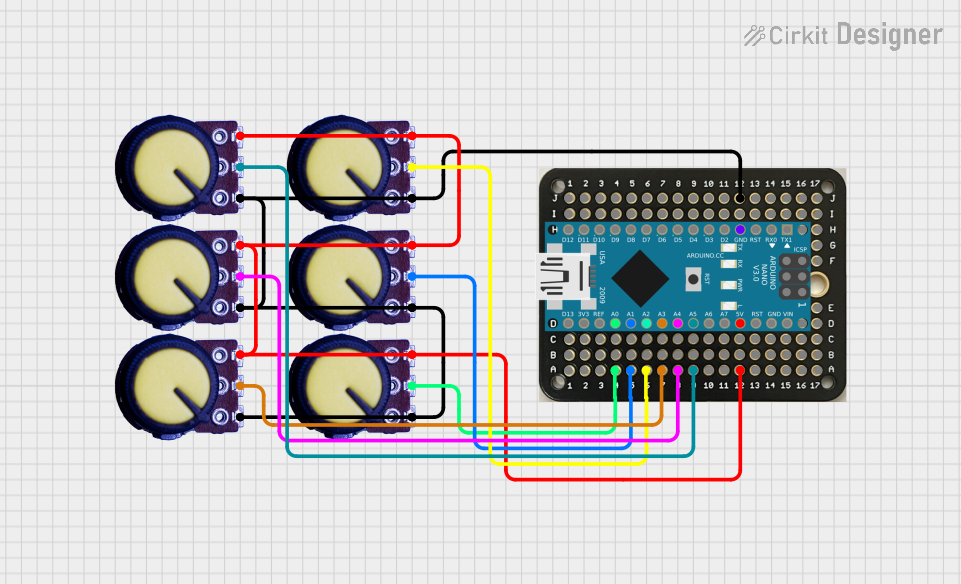
This circuit features an Arduino Nano connected to six potentiometers, each providing an analog input to the microcontroller. The Arduino reads the positions of the potentiometers and sends their values over a serial connection, likely for controlling volume or other parameters in software. The code suggests that this setup is configured for a volume mixer application, where each potentiometer corresponds to the volume level of a different audio channel or application.
Teensy 4.1-Based Multi-Channel Analog Input System with Potentiometer Control

This circuit is a multi-channel analog input system that uses a Teensy 4.1 microcontroller to read multiple potentiometers through an 8-channel and a 16-channel multiplexer. The circuit includes voltage regulation using an AMS1117 3.3V regulator and capacitors for power stabilization.
Explore Projects Built with Dual Digital Pot V1.0
Adafruit Circuit Playground-Based Interactive Control System with Pushbutton and Slide Potentiometers
This circuit features an Adafruit Circuit Playground Dev Edition microcontroller interfaced with a pushbutton and two slide potentiometers. The pushbutton is connected to digital pin D6, while the potentiometers provide analog input to pins D9 and D10, allowing for variable control inputs.
Analog Multiplexer-Based Multi-Potentiometer Control System
This circuit consists of two 16-channel analog multiplexers, each connected to 16 rotary potentiometers. The potentiometers' wiper terminals are connected to the multiplexer channels, allowing the multiplexers to select and output the analog voltage from any of the potentiometers.
Arduino Nano-Based Multi-Channel Volume Controller
This circuit features an Arduino Nano connected to six potentiometers, each providing an analog input to the microcontroller. The Arduino reads the positions of the potentiometers and sends their values over a serial connection, likely for controlling volume or other parameters in software. The code suggests that this setup is configured for a volume mixer application, where each potentiometer corresponds to the volume level of a different audio channel or application.
Teensy 4.1-Based Multi-Channel Analog Input System with Potentiometer Control
This circuit is a multi-channel analog input system that uses a Teensy 4.1 microcontroller to read multiple potentiometers through an 8-channel and a 16-channel multiplexer. The circuit includes voltage regulation using an AMS1117 3.3V regulator and capacitors for power stabilization.
Technical Specifications
Key Technical Details
| Parameter | Value |
|---|---|
| Supply Voltage | 2.7V to 5.5V |
| Resistance Range | 10kΩ |
| Number of Channels | 2 |
| Interface | I2C |
| Operating Current | 1mA (typical) |
| Operating Temperature | -40°C to +85°C |
Pin Configuration and Descriptions
| Pin Number | Pin Name | Description |
|---|---|---|
| 1 | VCC | Power supply (2.7V to 5.5V) |
| 2 | GND | Ground |
| 3 | SDA | I2C data line |
| 4 | SCL | I2C clock line |
| 5 | A0 | I2C address bit 0 |
| 6 | A1 | I2C address bit 1 |
| 7 | WP | Write protect (connect to GND for normal use) |
| 8 | NC | Not connected |
Usage Instructions
How to Use the Component in a Circuit
- Power Supply: Connect the VCC pin to a 3.3V or 5V power supply and the GND pin to the ground.
- I2C Interface: Connect the SDA and SCL pins to the corresponding I2C pins on your microcontroller (e.g., Arduino UNO).
- Address Configuration: Set the I2C address by connecting A0 and A1 to either VCC or GND. This allows for up to four unique addresses.
- Write Protect: Connect the WP pin to GND for normal operation.
Important Considerations and Best Practices
- Power Supply: Ensure the power supply voltage is within the specified range (2.7V to 5.5V).
- I2C Pull-up Resistors: Use appropriate pull-up resistors (typically 4.7kΩ) on the SDA and SCL lines.
- Address Configuration: Properly configure the I2C address to avoid conflicts with other I2C devices on the same bus.
- Write Protect: Keep the WP pin connected to GND unless write protection is required.
Example Code for Arduino UNO
#include <Wire.h>

#define POT_I2C_ADDRESS 0x2C // Adjust based on A0 and A1 configuration

void setup() {
  Wire.begin(); // Initialize I2C communication
  Serial.begin(9600); // Initialize serial communication for debugging
}

void loop() {
  setPotentiometer(0, 128); // Set channel 0 to mid-scale (128 out of 255)
  delay(1000); // Wait for 1 second
  setPotentiometer(1, 64); // Set channel 1 to quarter-scale (64 out of 255)
  delay(1000); // Wait for 1 second
}

void setPotentiometer(uint8_t channel, uint8_t value) {
  Wire.beginTransmission(POT_I2C_ADDRESS);
  Wire.write(channel); // Select the channel (0 or 1)
  Wire.write(value); // Set the resistance value (0 to 255)
  Wire.endTransmission();
  Serial.print("Channel ");
  Serial.print(channel);
  Serial.print(" set to ");
  Serial.println(value);
}
Troubleshooting and FAQs
Common Issues Users Might Face
No Response from the Potentiometer:
- Solution: Check the power supply connections and ensure the I2C address is correctly configured.
Incorrect Resistance Values:
- Solution: Verify the I2C communication and ensure the correct values are being sent to the potentiometer.
I2C Communication Errors:
- Solution: Ensure proper pull-up resistors are used on the SDA and SCL lines. Check for address conflicts with other I2C devices.
Solutions and Tips for Troubleshooting
- Check Connections: Ensure all connections are secure and correctly wired.
- Verify Power Supply: Confirm the power supply voltage is within the specified range.
- Use Serial Debugging: Utilize serial print statements to debug and monitor the I2C communication.
- Consult the Datasheet: Refer to the manufacturer's datasheet for detailed information and advanced configurations.
By following this documentation, users can effectively integrate and utilize the Dual Digital Pot V1.0 in their electronic projects, ensuring precise control over resistance values for various applications.