How to Use 1S/1A Brushed ESC: Examples, Pinouts, and Specs
Introduction
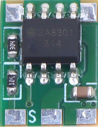
The 1S/1A Brushed Electronic Speed Controller (ESC) is a compact and lightweight device designed to regulate the speed, direction, and braking of brushed DC motors. Manufactured by Generic under the part ID "NoName," this ESC is ideal for low-power applications such as micro RC vehicles, drones, and robotics. It operates on a single-cell (1S) LiPo battery and supports a maximum continuous current of 1A, making it suitable for small-scale projects requiring precise motor control.
Explore Projects Built with 1S/1A Brushed ESC


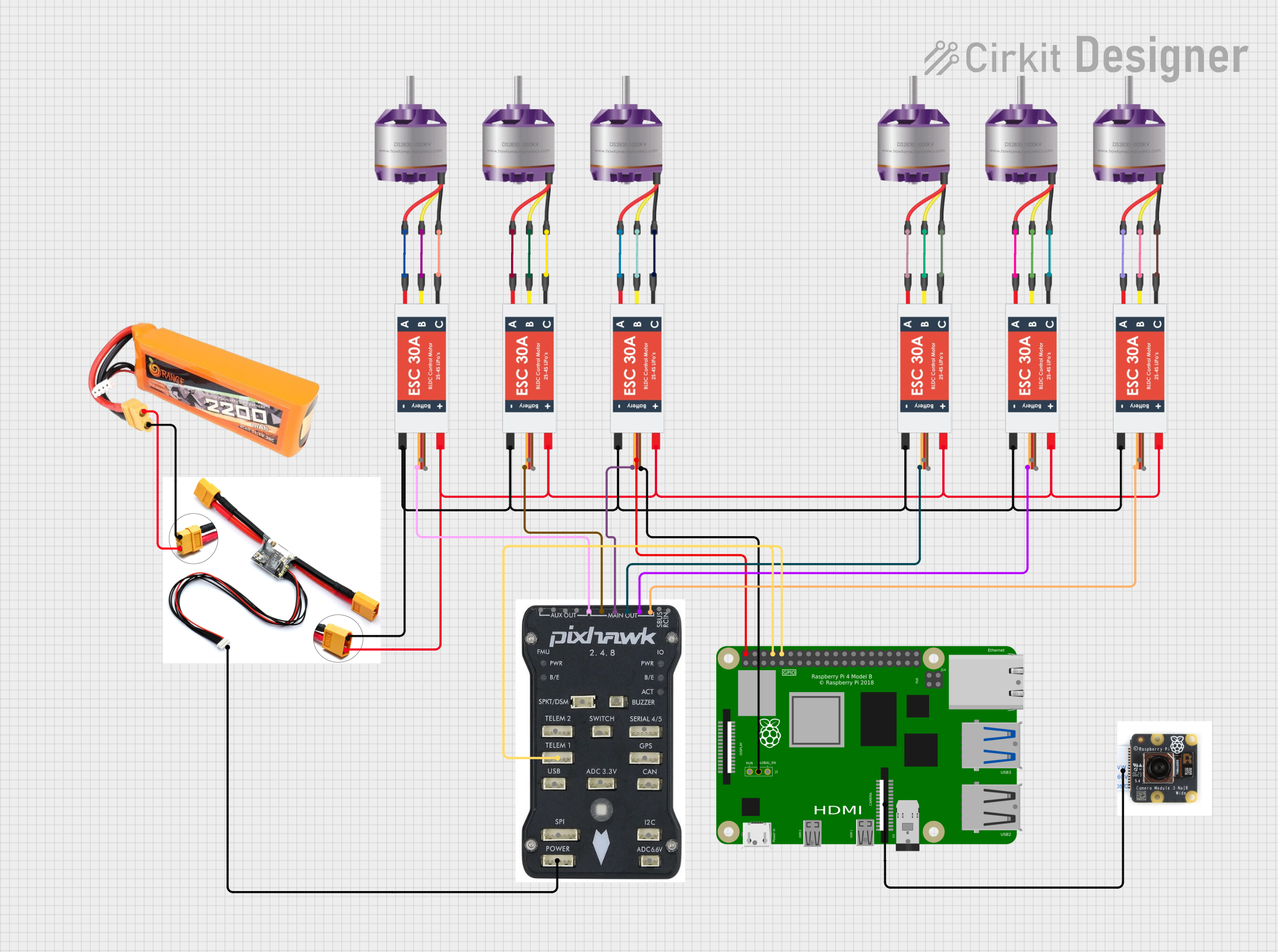

Explore Projects Built with 1S/1A Brushed ESC
Common Applications and Use Cases
- Micro RC cars, boats, and drones
- Robotics and automation projects
- Educational and DIY electronics
- Small brushed DC motor control in hobbyist applications
Technical Specifications
The following table outlines the key technical details of the 1S/1A Brushed ESC:
| Parameter | Specification |
|---|---|
| Input Voltage | 3.7V (1S LiPo battery) |
| Continuous Current | 1A |
| Peak Current | 2A (for short durations) |
| Motor Type Supported | Brushed DC motors |
| Control Signal Input | PWM (Pulse Width Modulation) |
| PWM Signal Range | 1ms to 2ms (standard RC signal) |
| Dimensions | 20mm x 10mm x 5mm |
| Weight | 2 grams |
Pin Configuration and Descriptions
The 1S/1A Brushed ESC has three main connectors:
| Pin/Connector Name | Description |
|---|---|
| Battery Input | Connects to a 1S LiPo battery (3.7V). Ensure correct polarity. |
| Motor Output | Connects to the brushed DC motor. Polarity determines motor direction. |
| Signal Input | Receives PWM signal from a microcontroller or RC receiver for speed control. |
Usage Instructions
How to Use the 1S/1A Brushed ESC in a Circuit
- Connect the Battery: Attach the battery to the ESC's battery input connector. Ensure the polarity is correct to avoid damage.
- Connect the Motor: Connect the two motor wires to the ESC's motor output terminals. If the motor spins in the wrong direction, reverse the connections.
- Connect the Signal Input: Use a microcontroller (e.g., Arduino UNO) or an RC receiver to send a PWM signal to the ESC's signal input pin.
- Power On: Turn on the power supply. The ESC will initialize and be ready to control the motor.
Important Considerations and Best Practices
- Voltage Compatibility: Only use a 1S LiPo battery (3.7V). Higher voltages may damage the ESC.
- Current Limitations: Ensure the motor's current draw does not exceed 1A continuously or 2A peak.
- Signal Calibration: Calibrate the ESC to match the PWM signal range of your controller for optimal performance.
- Heat Management: Avoid prolonged operation at maximum current to prevent overheating.
- Polarity Check: Double-check all connections to avoid reversing polarity, which can damage the ESC.
Example: Using the 1S/1A Brushed ESC with an Arduino UNO
Below is an example Arduino sketch to control the ESC using a PWM signal:
// Example code to control a 1S/1A Brushed ESC with Arduino UNO
// Connect the ESC signal input to Arduino pin 9

#include <Servo.h> // Include the Servo library to generate PWM signals

Servo esc; // Create a Servo object to control the ESC

void setup() {
  esc.attach(9); // Attach the ESC signal wire to pin 9
  esc.writeMicroseconds(1000); // Send minimum throttle (1ms PWM signal)
  delay(2000); // Wait for 2 seconds to allow the ESC to initialize
}

void loop() {
  esc.writeMicroseconds(1500); // Set motor speed to 50% (1.5ms PWM signal)
  delay(5000); // Run motor at 50% speed for 5 seconds

  esc.writeMicroseconds(2000); // Set motor speed to 100% (2ms PWM signal)
  delay(5000); // Run motor at full speed for 5 seconds

  esc.writeMicroseconds(1000); // Stop the motor (1ms PWM signal)
  delay(5000); // Wait for 5 seconds before repeating
}
Notes:
- Replace
9inesc.attach(9)with the appropriate pin number if using a different Arduino pin. - Ensure the ESC is properly calibrated to the PWM signal range (1ms to 2ms) before running the code.
Troubleshooting and FAQs
Common Issues and Solutions
Motor Does Not Spin
- Cause: Incorrect wiring or insufficient power supply.
- Solution: Verify all connections and ensure the battery is charged.
Motor Spins in the Wrong Direction
- Cause: Motor wires are connected in reverse.
- Solution: Swap the two motor wires to reverse the direction.
ESC Overheats
- Cause: Motor is drawing more current than the ESC's rated capacity.
- Solution: Use a motor with a lower current draw or reduce the load on the motor.
No Response from ESC
- Cause: Incorrect PWM signal or signal wire not connected.
- Solution: Check the PWM signal range and ensure the signal wire is properly connected.
ESC Beeps Continuously
- Cause: ESC is not receiving a valid PWM signal.
- Solution: Verify the connection between the ESC and the microcontroller or RC receiver.
FAQs
Q: Can I use this ESC with a 2S LiPo battery?
A: No, this ESC is designed for 1S (3.7V) LiPo batteries only. Using a higher voltage may damage the ESC.
Q: How do I calibrate the ESC?
A: To calibrate, send the maximum and minimum PWM signals (e.g., 2ms and 1ms) during initialization. Refer to the ESC's specific calibration procedure if available.
Q: Can I control multiple motors with one ESC?
A: No, this ESC is designed to control a single brushed DC motor. Use separate ESCs for multiple motors.
Q: Is this ESC compatible with brushless motors?
A: No, this ESC is specifically designed for brushed DC motors. Use a brushless ESC for brushless motors.