How to Use Bus PCB: Examples, Pinouts, and Specs
Introduction
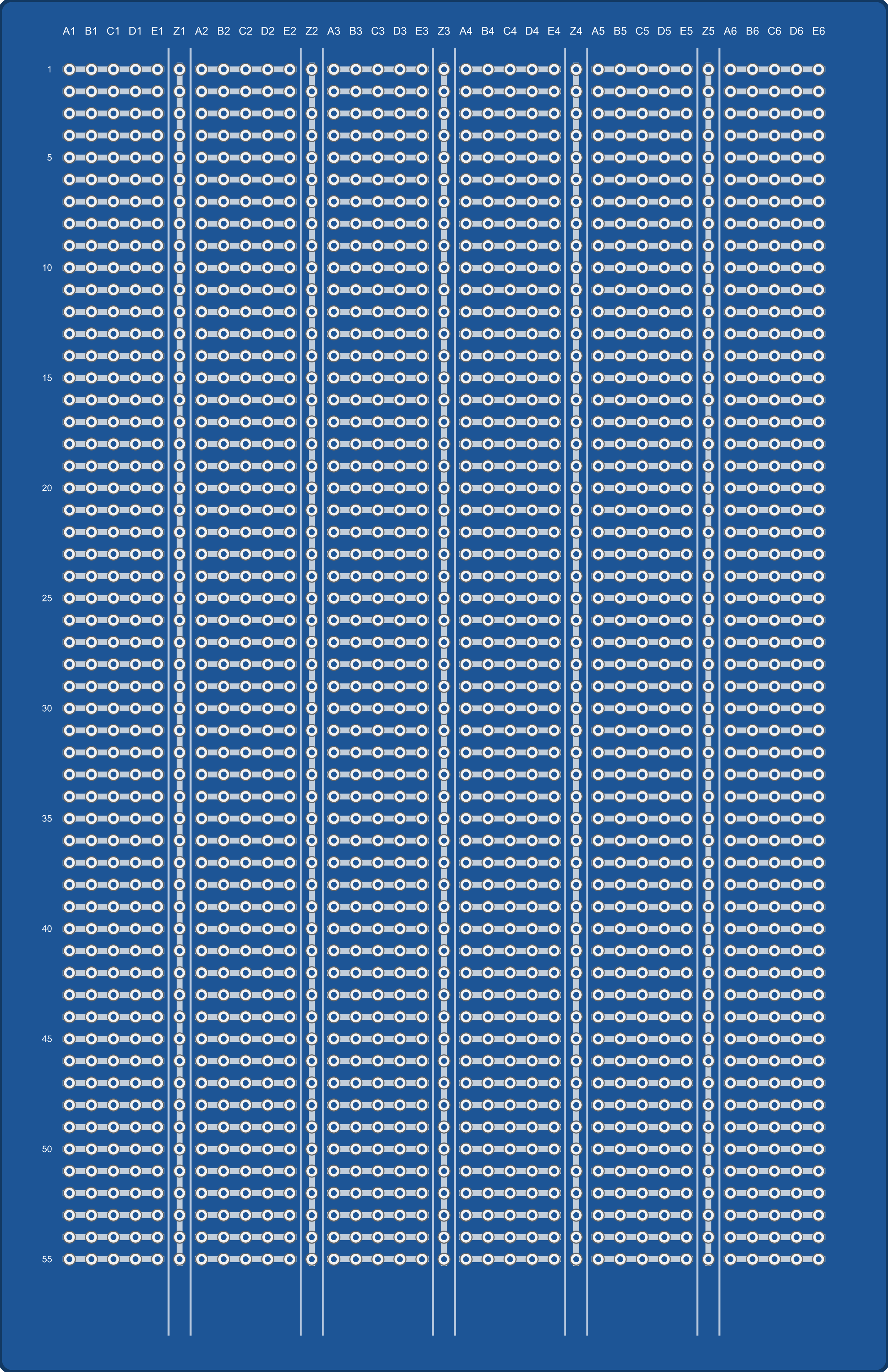
A Bus PCB (Printed Circuit Board) is a specialized circuit board designed to enable communication between multiple electronic components or systems. It serves as a backbone for data transfer and signal routing, ensuring efficient and organized connectivity in complex electronic designs. Bus PCBs are commonly used in applications such as computer motherboards, industrial control systems, automotive electronics, and communication devices.
Explore Projects Built with Bus PCB


Explore Projects Built with Bus PCB
Common Applications and Use Cases
- Computer Systems: Used in motherboards to connect CPUs, memory, and peripherals.
- Industrial Automation: Facilitates communication between sensors, controllers, and actuators.
- Automotive Electronics: Enables communication between ECUs (Electronic Control Units).
- Communication Devices: Provides signal routing in networking equipment like routers and switches.
Technical Specifications
Key Technical Details
- Material: FR4 (common), Rogers (high-frequency applications), or other PCB substrates.
- Layers: Typically 2 to 16 layers, depending on complexity.
- Operating Voltage: Varies based on application, typically 3.3V, 5V, or 12V.
- Signal Integrity: Designed for high-speed data transfer with minimal interference.
- Trace Width and Spacing: Determined by current capacity and signal requirements.
- Connector Types: May include edge connectors, pin headers, or custom connectors.
Pin Configuration and Descriptions
The pin configuration of a Bus PCB depends on its specific design and application. Below is an example of a generic Bus PCB with a 10-pin header for communication:
| Pin Number | Pin Name | Description |
|---|---|---|
| 1 | VCC | Power supply (e.g., 3.3V or 5V) |
| 2 | GND | Ground connection |
| 3 | DATA_IN | Input data line |
| 4 | DATA_OUT | Output data line |
| 5 | CLK | Clock signal for synchronization |
| 6 | RESET | Reset signal for connected devices |
| 7 | ENABLE | Enable signal to activate communication |
| 8 | INTERRUPT | Interrupt signal for event-driven communication |
| 9 | RESERVED | Reserved for future use or custom functionality |
| 10 | NC (No Connect) | Not connected (can be left floating) |
Usage Instructions
How to Use the Component in a Circuit
- Power Supply: Connect the VCC and GND pins to the appropriate power source. Ensure the voltage matches the specifications of the Bus PCB.
- Signal Connections: Connect the DATA_IN, DATA_OUT, and CLK pins to the corresponding components or systems.
- Enable Communication: Use the ENABLE pin to activate the bus. This may involve pulling the pin high or low, depending on the design.
- Reset Functionality: If required, connect the RESET pin to a microcontroller or external reset circuit.
- Interrupt Handling: Use the INTERRUPT pin to handle event-driven communication, such as signaling when data is ready.
Important Considerations and Best Practices
- Signal Integrity: Use proper trace widths and spacing to minimize crosstalk and signal degradation, especially for high-speed signals.
- Termination Resistors: Add termination resistors to prevent signal reflections on long traces.
- Grounding: Ensure a solid ground plane to reduce noise and improve performance.
- Connector Quality: Use high-quality connectors to ensure reliable connections.
- Testing: Verify the PCB design with simulation tools before manufacturing.
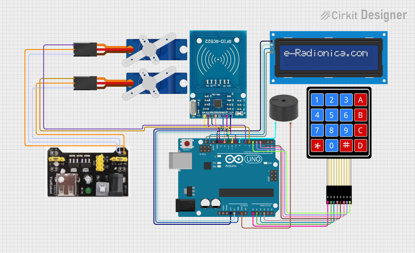
Example: Connecting a Bus PCB to an Arduino UNO
Below is an example of how to connect a Bus PCB to an Arduino UNO for basic communication:
Circuit Connections
- Connect the VCC pin of the Bus PCB to the 5V pin on the Arduino.
- Connect the GND pin of the Bus PCB to the GND pin on the Arduino.
- Connect the DATA_IN pin of the Bus PCB to Arduino digital pin 2.
- Connect the DATA_OUT pin of the Bus PCB to Arduino digital pin 3.
- Connect the CLK pin of the Bus PCB to Arduino digital pin 4.
Arduino Code Example
// Example code for interfacing a Bus PCB with Arduino UNO
// This code demonstrates basic data transmission and reception

#define DATA_IN_PIN 2  // Pin connected to DATA_IN on the Bus PCB
#define DATA_OUT_PIN 3 // Pin connected to DATA_OUT on the Bus PCB
#define CLK_PIN 4      // Pin connected to CLK on the Bus PCB

void setup() {
  pinMode(DATA_IN_PIN, INPUT);  // Set DATA_IN as input
  pinMode(DATA_OUT_PIN, OUTPUT); // Set DATA_OUT as output
  pinMode(CLK_PIN, OUTPUT);     // Set CLK as output

  digitalWrite(CLK_PIN, LOW);   // Initialize clock signal to LOW
  Serial.begin(9600);           // Start serial communication for debugging
}

void loop() {
  // Example: Sending data to the Bus PCB
  digitalWrite(CLK_PIN, HIGH);  // Generate clock pulse
  delayMicroseconds(10);        // Short delay for synchronization
  digitalWrite(CLK_PIN, LOW);

  digitalWrite(DATA_OUT_PIN, HIGH); // Send a HIGH signal
  delay(1000);                      // Wait for 1 second
  digitalWrite(DATA_OUT_PIN, LOW);  // Send a LOW signal
  delay(1000);

  // Example: Reading data from the Bus PCB
  int data = digitalRead(DATA_IN_PIN); // Read data from DATA_IN
  Serial.print("Received Data: ");
  Serial.println(data);                // Print received data to Serial Monitor
}
Troubleshooting and FAQs
Common Issues and Solutions
No Communication Between Components
- Cause: Incorrect wiring or loose connections.
- Solution: Double-check all connections and ensure proper pin mapping.
Signal Interference or Noise
- Cause: Poor grounding or improper trace design.
- Solution: Use a solid ground plane and ensure proper trace spacing.
Data Loss or Corruption
- Cause: High-speed signals without proper termination.
- Solution: Add termination resistors to the bus lines.
Overheating
- Cause: Exceeding the power rating of the PCB.
- Solution: Ensure the power supply voltage and current are within specifications.
FAQs
Q: Can I use a Bus PCB for analog signals?
A: Yes, but ensure the design accounts for signal integrity and noise reduction.Q: How do I choose the right Bus PCB for my application?
A: Consider factors such as the number of layers, operating voltage, and connector type.Q: Can I use a Bus PCB with a Raspberry Pi?
A: Yes, as long as the voltage levels and pin configurations are compatible.Q: What tools can I use to design a Bus PCB?
A: Popular tools include KiCad, Eagle, and Altium Designer.