Cirkit Designer Logo
Cirkit Designer
Your all-in-one circuit design IDE
Home / 
Component Documentation

How to Use Micro Switch: Examples, Pinouts, and Specs

Image of Micro Switch
Cirkit Designer LogoDesign with Micro Switch in Cirkit Designer

Introduction

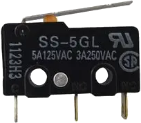
A micro switch, also known as a miniature snap-action switch, is a small, high-precision switch that operates using a tipping-point mechanism with very little physical force. It is widely used in various applications, including home appliances, industrial equipment, and consumer electronics, to detect the presence or absence of objects, changes in position, or to provide a user with tactile feedback.

Explore Projects Built with Micro Switch

Use Cirkit Designer to design, explore, and prototype these projects online. Some projects support real-time simulation. Click "Open Project" to start designing instantly!
Arduino-Controlled Input Panel with Momentary and Toggle Switches
Image of button box group 2: A project utilizing Micro Switch in a practical application
This circuit features an Arduino Micro Pro microcontroller connected to multiple input devices including momentary switches and rotary encoders, with toggle switches likely used for controlling power or signal paths. The microcontroller is set up to monitor and respond to the state changes of these input devices, enabling interactive control for an application.
Cirkit Designer LogoOpen Project in Cirkit Designer
Toggle Switch Controlled Lamp Circuit with Banana Sockets
Image of STAIRCASE: A project utilizing Micro Switch in a practical application
This circuit consists of two toggle switches and a red lamp connected to panel mount banana sockets. The switches control the connection between the red and black banana sockets, allowing the lamp to be turned on or off depending on the switch positions.
Cirkit Designer LogoOpen Project in Cirkit Designer
SparkFun Pro Micro with Micro Switch Interface
Image of button_2: A project utilizing Micro Switch in a practical application
This circuit consists of a SparkFun Pro Micro microcontroller connected to a micro switch. The common (COM) terminal of the switch is connected to the ground (GND) of the microcontroller, and the normally open (NO) terminal is connected to digital pin D10 on the Pro Micro. The circuit is likely designed to detect a switch press, which the microcontroller can then respond to programmatically.
Cirkit Designer LogoOpen Project in Cirkit Designer
Arduino-Controlled Input Interface with Momentary Switches and Rotary Encoders
Image of  button box: A project utilizing Micro Switch in a practical application
This circuit includes an array of momentary switches (both red and black), toggle switches, and rotary encoders, all interfaced with an Arduino Micro Pro microcontroller. The momentary switches and toggle switches are likely used for input commands, while the rotary encoders provide both rotational position input and additional switch inputs. The microcontroller's pins are connected to the signal pins of these input devices, suggesting that it is configured to read their states and react accordingly, although without embedded code, the specific behavior cannot be determined.
Cirkit Designer LogoOpen Project in Cirkit Designer

Explore Projects Built with Micro Switch

Use Cirkit Designer to design, explore, and prototype these projects online. Some projects support real-time simulation. Click "Open Project" to start designing instantly!
Image of button box group 2: A project utilizing Micro Switch in a practical application
Arduino-Controlled Input Panel with Momentary and Toggle Switches
This circuit features an Arduino Micro Pro microcontroller connected to multiple input devices including momentary switches and rotary encoders, with toggle switches likely used for controlling power or signal paths. The microcontroller is set up to monitor and respond to the state changes of these input devices, enabling interactive control for an application.
Cirkit Designer LogoOpen Project in Cirkit Designer
Image of STAIRCASE: A project utilizing Micro Switch in a practical application
Toggle Switch Controlled Lamp Circuit with Banana Sockets
This circuit consists of two toggle switches and a red lamp connected to panel mount banana sockets. The switches control the connection between the red and black banana sockets, allowing the lamp to be turned on or off depending on the switch positions.
Cirkit Designer LogoOpen Project in Cirkit Designer
Image of button_2: A project utilizing Micro Switch in a practical application
SparkFun Pro Micro with Micro Switch Interface
This circuit consists of a SparkFun Pro Micro microcontroller connected to a micro switch. The common (COM) terminal of the switch is connected to the ground (GND) of the microcontroller, and the normally open (NO) terminal is connected to digital pin D10 on the Pro Micro. The circuit is likely designed to detect a switch press, which the microcontroller can then respond to programmatically.
Cirkit Designer LogoOpen Project in Cirkit Designer
Image of  button box: A project utilizing Micro Switch in a practical application
Arduino-Controlled Input Interface with Momentary Switches and Rotary Encoders
This circuit includes an array of momentary switches (both red and black), toggle switches, and rotary encoders, all interfaced with an Arduino Micro Pro microcontroller. The momentary switches and toggle switches are likely used for input commands, while the rotary encoders provide both rotational position input and additional switch inputs. The microcontroller's pins are connected to the signal pins of these input devices, suggesting that it is configured to read their states and react accordingly, although without embedded code, the specific behavior cannot be determined.
Cirkit Designer LogoOpen Project in Cirkit Designer

Common Applications and Use Cases

  • Safety interlocks in appliances (e.g., microwave door switches)
  • Position sensing in machinery (e.g., CNC machines)
  • End-stop switches in 3D printers
  • Level switches in vending machines
  • Keyboard keys in computer peripherals

Technical Specifications

Key Technical Details

  • Voltage Rating: Typically ranges from 5V to 250V
  • Current Rating: Can vary from a few milliamps to around 10-15A
  • Contact Configuration: Normally open (NO), normally closed (NC), or changeover (SPDT)
  • Operating Force: The force required to actuate the switch, usually measured in grams or newtons
  • Mechanical Life: The number of actuations the switch can endure, often in the millions

Pin Configuration and Descriptions

Pin Number Description Notes
1 Common (COM) Connects to the moving contact
2 Normally Open (NO) Closed when the actuator is engaged
3 Normally Closed (NC) Closed when the actuator is at rest

Usage Instructions

How to Use the Micro Switch in a Circuit

  1. Identify the Pins: Refer to the pin configuration table to identify the Common (COM), Normally Open (NO), and Normally Closed (NC) pins.
  2. Wiring: Connect the COM pin to one side of the control circuit. Connect either the NO or NC pin to the other side, depending on whether you want the circuit to be closed by default or only when the switch is actuated.
  3. Mounting: Secure the micro switch in place so that the actuator will be properly engaged by the moving part of your application.
  4. Testing: Before finalizing the installation, test the switch to ensure it actuates correctly and the circuit behaves as expected.

Important Considerations and Best Practices

  • Voltage and Current Ratings: Do not exceed the voltage and current ratings specified for the micro switch to avoid damage.
  • Debouncing: Micro switches inherently provide a clean contact bounce profile, but in sensitive applications, consider implementing debouncing techniques.
  • Environmental Factors: Consider the operating environment. Micro switches rated for high temperatures or with protective sealing may be necessary in harsh conditions.

Troubleshooting and FAQs

Common Issues

  • Intermittent Operation: This could be due to a loose connection or a worn-out switch. Check the wiring and replace the switch if necessary.
  • No Actuation: Ensure that the actuator is properly engaged and that there is no obstruction. Also, verify that the switch is not damaged.

Solutions and Tips for Troubleshooting

  • Check Connections: Loose or corroded connections can cause issues. Inspect and clean or tighten connections as needed.
  • Test with a Multimeter: Use a multimeter to check for continuity across the COM and NO/NC pins when the switch is actuated.
  • Replace if Faulty: If the switch does not show continuity where expected or shows continuity without actuation, replace it.

FAQs

Q: Can I use a micro switch with an Arduino? A: Yes, micro switches can be used with an Arduino for input detection. Ensure that the switch's voltage and current ratings are compatible with the Arduino's I/O pins.

Q: How do I know if my micro switch is working? A: You can test it with a multimeter set to the continuity function. When the actuator is pressed, you should hear a beep if the switch is functioning correctly.

Q: What is the difference between NO and NC contacts? A: NO contacts are open when the switch is at rest and close when actuated. NC contacts are closed at rest and open when actuated.

Example Arduino Code

// Define the pin connected to the micro switch
const int microSwitchPin = 2;

void setup() {
  // Set the micro switch pin as an input
  pinMode(microSwitchPin, INPUT_PULLUP);
  Serial.begin(9600);
}

void loop() {
  // Read the state of the micro switch
  int switchState = digitalRead(microSwitchPin);

  // Check if the switch is pressed (assuming NO configuration)
  if (switchState == LOW) {
    // The switch is pressed
    Serial.println("Switch is pressed");
  } else {
    // The switch is not pressed
    Serial.println("Switch is not pressed");
  }

  // Add a small delay to prevent bouncing issues
  delay(50);
}

Note: The INPUT_PULLUP mode is used to enable the internal pull-up resistor, which ensures a stable state when the switch is open. The switch is connected between the pin and ground. When pressed, the pin reads LOW; when released, it reads HIGH due to the pull-up resistor.