How to Use Charger 3.7V 1A: Examples, Pinouts, and Specs
Introduction
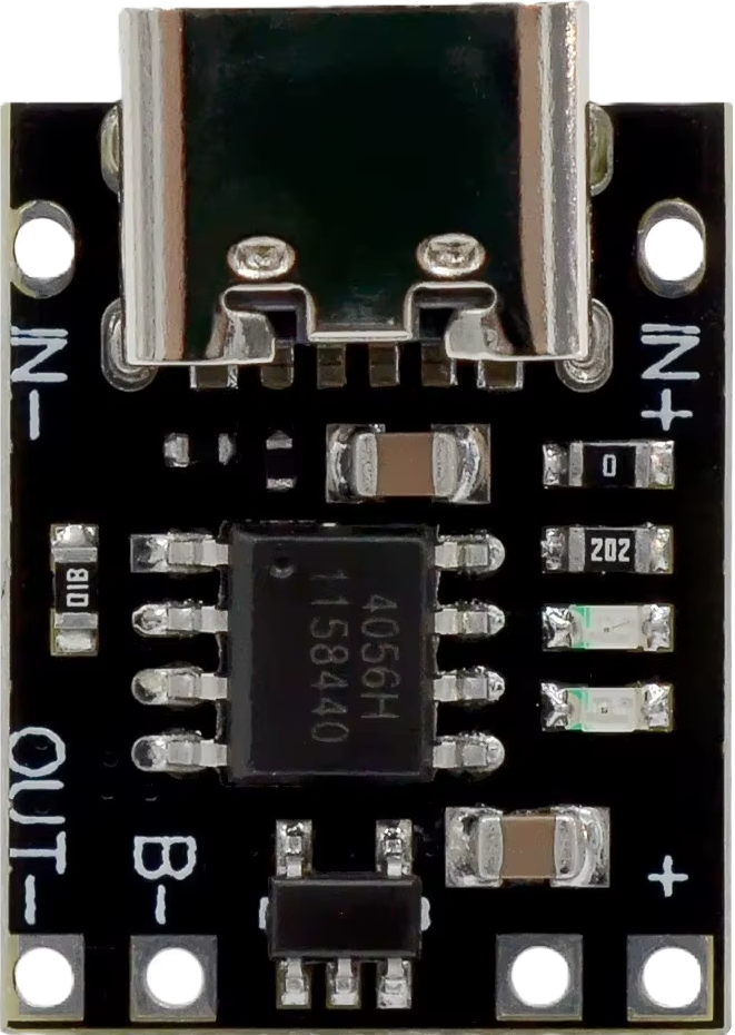
The Charger 3.7V 1A is a power supply device specifically designed to charge lithium-ion batteries with a nominal voltage of 3.7V. It provides a maximum current output of 1A, ensuring efficient and safe charging. This component is widely used in portable electronics, DIY projects, and battery-powered devices due to its compact size and reliable performance.
Explore Projects Built with Charger 3.7V 1A


Explore Projects Built with Charger 3.7V 1A
Common Applications and Use Cases
- Charging single-cell lithium-ion or lithium-polymer batteries.
- Powering small electronic devices such as wearables, IoT devices, and handheld gadgets.
- Integration into battery management systems for DIY projects.
- Use in robotics and portable power banks.
Technical Specifications
Below are the key technical details and pin configuration for the Charger 3.7V 1A:
Key Technical Details
| Parameter | Value |
|---|---|
| Input Voltage Range | 4.5V to 6V (typically 5V) |
| Output Voltage | 4.2V (regulated for charging) |
| Maximum Output Current | 1A |
| Charging Method | Constant Current / Constant Voltage (CC/CV) |
| Battery Compatibility | 3.7V lithium-ion or lithium-polymer batteries |
| Efficiency | Up to 90% |
| Operating Temperature | -10°C to 60°C |
| Dimensions | Varies (commonly compact, e.g., 25mm x 15mm) |
Pin Configuration and Descriptions
| Pin Name | Description |
|---|---|
| VCC | Input power supply pin (4.5V to 6V, typically connected to a USB 5V source). |
| GND | Ground pin for the input and output. |
| BAT+ | Positive terminal for the battery connection. |
| BAT- | Negative terminal for the battery connection. |
| STAT | Status indicator pin (optional, used for LED indication of charging state). |
Usage Instructions
How to Use the Charger 3.7V 1A in a Circuit
- Power Input: Connect the VCC pin to a 5V power source, such as a USB port or a regulated power supply. Ensure the input voltage does not exceed 6V.
- Battery Connection:
- Connect the BAT+ pin to the positive terminal of the 3.7V lithium-ion battery.
- Connect the BAT- pin to the negative terminal of the battery.
- Status Indicator (Optional): If the module includes a STAT pin, you can connect an LED to monitor the charging status:
- LED ON: Charging in progress.
- LED OFF: Charging complete or no battery connected.
- Safety Precautions:
- Ensure the battery is compatible with the charger (3.7V nominal voltage).
- Avoid short-circuiting the BAT+ and BAT- pins.
- Do not exceed the maximum input voltage of 6V.
Important Considerations and Best Practices
- Heat Management: The charger may heat up during operation, especially at higher currents. Ensure proper ventilation or heat dissipation.
- Battery Protection: Use batteries with built-in protection circuits to prevent overcharging, over-discharging, and short circuits.
- Input Power Source: Use a stable and regulated power source to avoid damaging the charger or the battery.
- Testing: Before connecting a battery, test the output voltage of the charger to ensure it is within the expected range (4.2V).
Example: Using the Charger with an Arduino UNO
While the Charger 3.7V 1A is not directly programmable, it can be used in conjunction with an Arduino UNO to monitor the charging process. Below is an example code to read the charging status using the STAT pin:
// Define the STAT pin connected to the charger module
const int statPin = 7; // Connect STAT pin to Arduino digital pin 7

void setup() {
  pinMode(statPin, INPUT); // Set STAT pin as input
  Serial.begin(9600);      // Initialize serial communication
}

void loop() {
  int chargingStatus = digitalRead(statPin); // Read the STAT pin state

  if (chargingStatus == LOW) {
    // STAT pin LOW indicates charging in progress
    Serial.println("Battery is charging...");
  } else {
    // STAT pin HIGH indicates charging complete or no battery connected
    Serial.println("Charging complete or no battery connected.");
  }

  delay(1000); // Wait for 1 second before checking again
}
Troubleshooting and FAQs
Common Issues and Solutions
Charger Not Powering On:
- Cause: Insufficient input voltage or loose connections.
- Solution: Verify the input voltage is within the 4.5V to 6V range and check all connections.
Battery Not Charging:
- Cause: Incorrect battery connection or incompatible battery.
- Solution: Ensure the battery terminals are correctly connected to BAT+ and BAT-. Verify the battery is a 3.7V lithium-ion or lithium-polymer type.
Overheating:
- Cause: Prolonged operation at maximum current or poor ventilation.
- Solution: Reduce the charging current if possible or improve ventilation around the charger.
LED Indicator Not Working:
- Cause: Faulty LED connection or damaged STAT pin.
- Solution: Check the LED wiring and ensure the STAT pin is functioning correctly.
FAQs
Q1: Can I use this charger for batteries with a different nominal voltage?
A1: No, this charger is specifically designed for 3.7V lithium-ion or lithium-polymer batteries. Using it with other battery types may result in damage or unsafe operation.
Q2: What happens if I exceed the 1A current limit?
A2: Exceeding the 1A limit may cause the charger to overheat or fail. Always ensure the battery and circuit do not draw more than 1A.
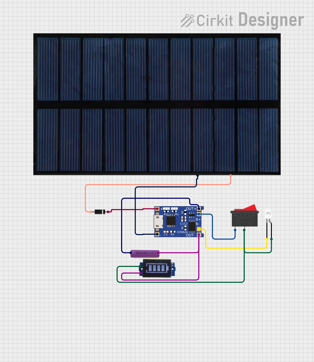
Q3: Can I use this charger with a solar panel?
A3: Yes, as long as the solar panel provides a stable output voltage within the 4.5V to 6V range. However, fluctuations in solar panel output may affect charging performance.
Q4: Is it safe to leave the battery connected after charging is complete?
A4: Yes, the charger includes overcharge protection and will stop charging once the battery reaches 4.2V. However, it is good practice to disconnect the battery when not in use.
This concludes the documentation for the Charger 3.7V 1A.