How to Use Alarm Cable: Examples, Pinouts, and Specs

Introduction
Alarm cables are specialized cables designed for use in security and alarm systems. They ensure reliable transmission of signals between various components, such as sensors, control panels, and sirens. These cables are typically constructed with multiple conductors and are often shielded to minimize interference, ensuring consistent performance in critical applications.
Explore Projects Built with Alarm Cable
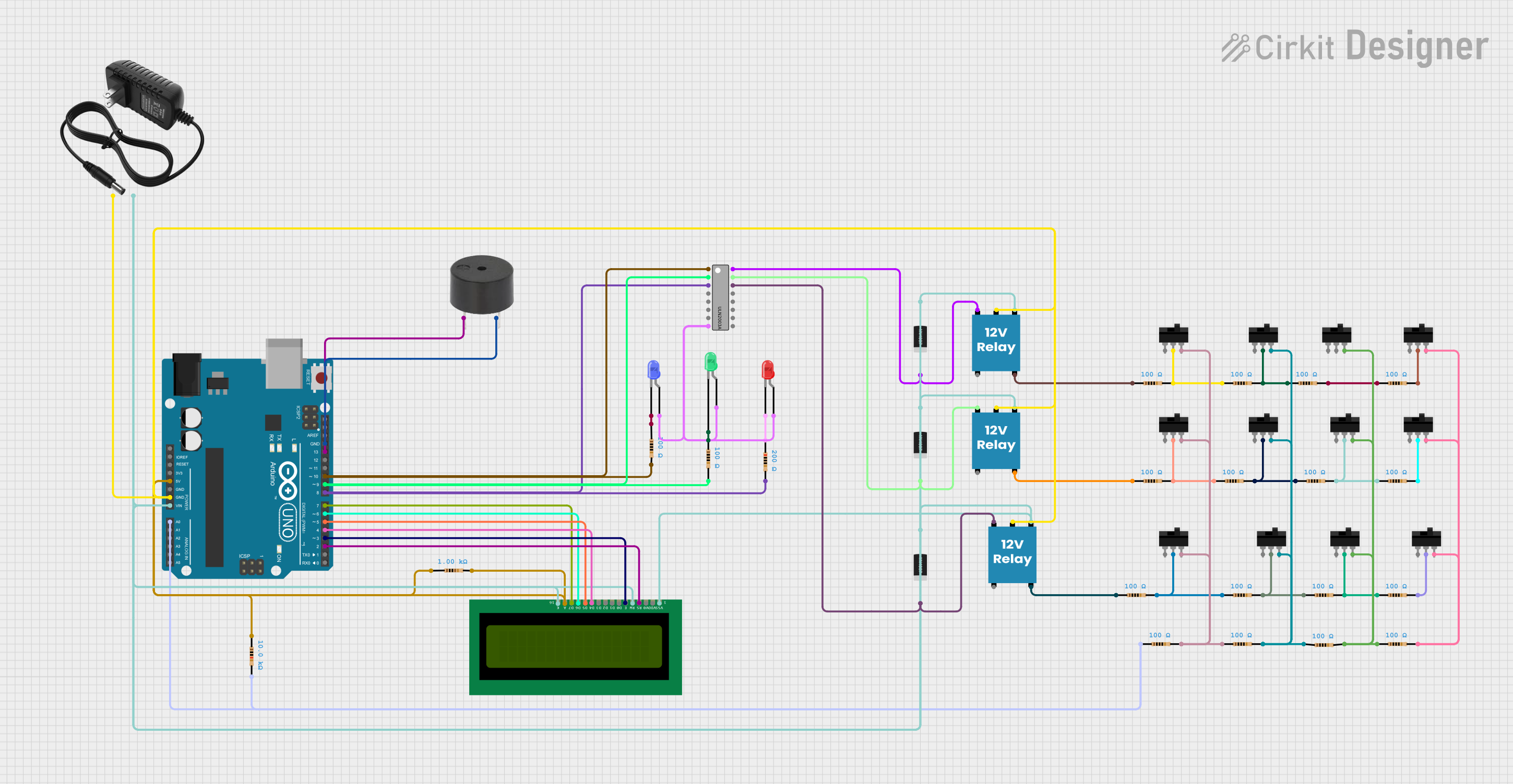

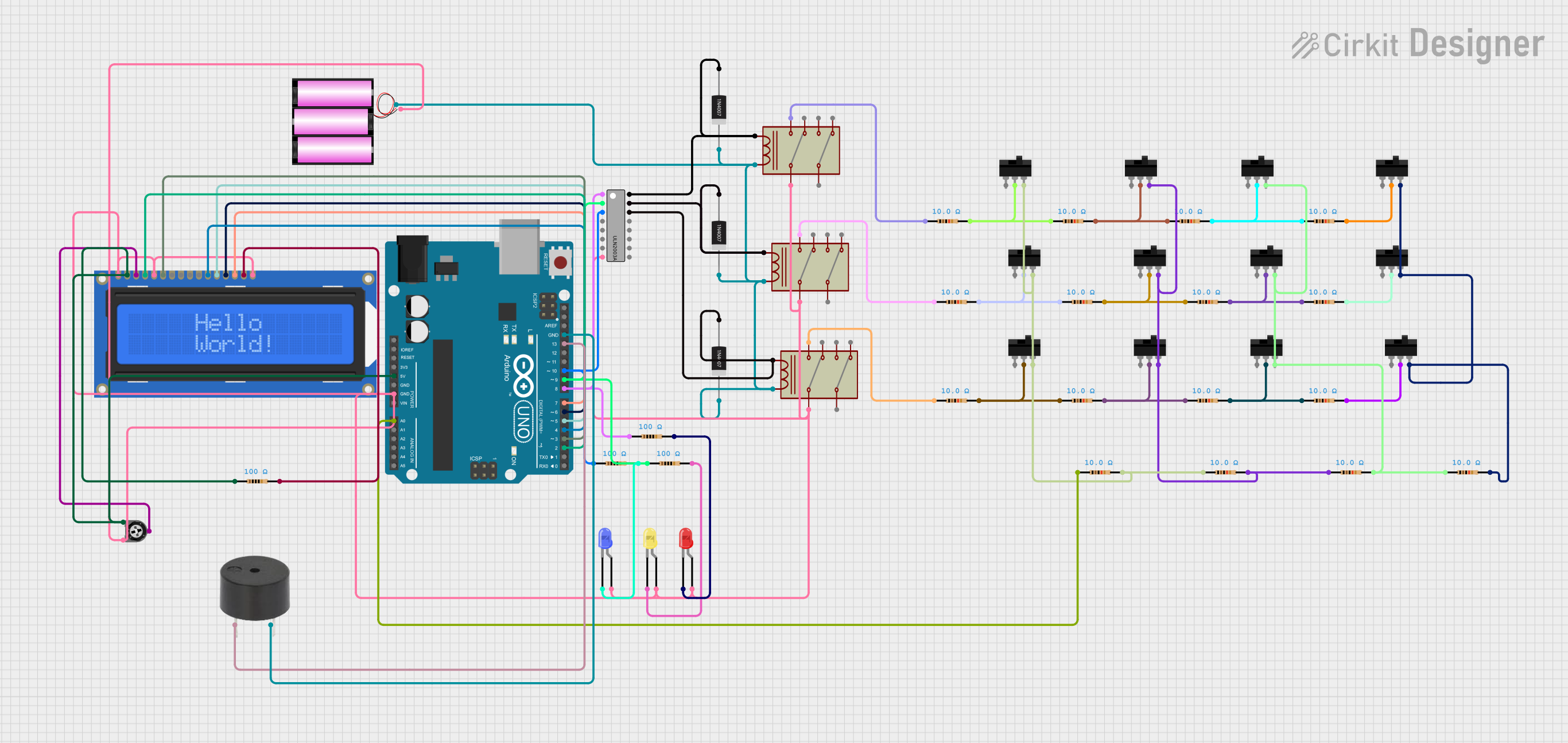
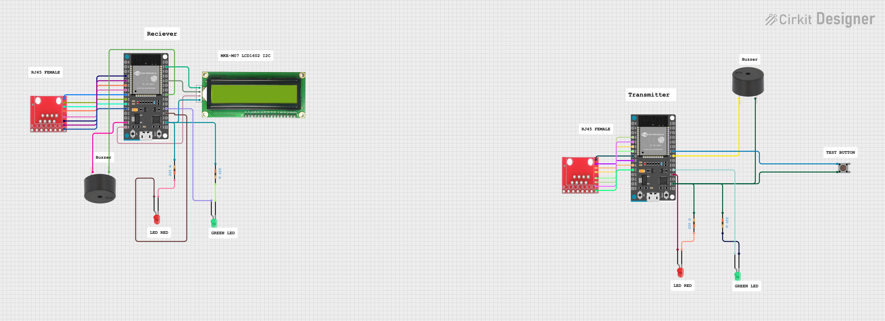
Explore Projects Built with Alarm Cable
Common Applications and Use Cases
- Security alarm systems in residential, commercial, and industrial settings
- Fire alarm systems for transmitting signals from detectors to control panels
- Intercom and access control systems
- CCTV systems for auxiliary connections
- Low-voltage control circuits
Technical Specifications
Alarm cables come in various configurations to suit different applications. Below are the general specifications for a standard alarm cable:
Key Technical Details
- Voltage Rating: Typically 12V to 24V DC (low voltage)
- Current Rating: Up to 2A per conductor (varies by cable type)
- Conductor Material: Copper (solid or stranded)
- Number of Conductors: 2 to 12 (or more, depending on the application)
- Conductor Gauge: 18 AWG to 24 AWG
- Insulation Material: PVC or LSZH (Low Smoke Zero Halogen)
- Shielding: Available in shielded and unshielded variants
- Operating Temperature: -20°C to +70°C
- Outer Jacket: PVC or LSZH for durability and fire resistance
Pin Configuration and Descriptions
Alarm cables do not have a fixed pin configuration, as they are used to connect various components. However, the table below provides a general guide for common conductor color codes and their typical uses:
| Conductor Color | Typical Use |
|---|---|
| Red | Positive power supply (+12V) |
| Black | Ground (GND) |
| White | Signal wire (e.g., sensor data) |
| Green | Signal wire (e.g., sensor data) |
| Yellow | Auxiliary signal wire |
| Blue | Auxiliary signal wire |
Note: Always refer to the specific wiring diagram of your alarm system for proper connections.
Usage Instructions
How to Use the Component in a Circuit
- Determine the Required Cable Type: Identify the number of conductors and shielding requirements based on your alarm system's specifications.
- Strip the Cable Ends: Use a wire stripper to carefully remove the outer jacket and expose the individual conductors.
- Connect to Components: Match the conductor colors to the corresponding terminals on the alarm system's sensors, control panel, or other devices.
- Secure the Connections: Use screw terminals, crimp connectors, or soldering to ensure reliable connections.
- Route the Cable: Run the cable along walls, ceilings, or conduits, ensuring it is protected from physical damage and interference.
- Test the System: Power on the alarm system and verify that all components are communicating correctly.
Important Considerations and Best Practices
- Cable Length: Ensure the cable length does not exceed the maximum supported by your system to avoid signal loss.
- Shielding: Use shielded cables in environments with high electromagnetic interference (EMI).
- Fire Safety: In critical installations, use LSZH cables to minimize toxic fumes in case of fire.
- Labeling: Clearly label both ends of the cable for easy identification during maintenance.
- Avoid Sharp Bends: Do not bend the cable sharply, as this can damage the conductors or insulation.
Example: Connecting an Alarm Cable to an Arduino UNO
If you are using an alarm cable to connect a sensor to an Arduino UNO, follow this example:
// Example code for reading a signal from a sensor connected via an alarm cable
// Connect the sensor's signal wire to Arduino pin 2, and power wires to 5V and GND.

const int sensorPin = 2;  // Pin connected to the sensor's signal wire
int sensorState = 0;      // Variable to store the sensor's state

void setup() {
  pinMode(sensorPin, INPUT);  // Set the sensor pin as an input
  Serial.begin(9600);         // Initialize serial communication
}

void loop() {
  sensorState = digitalRead(sensorPin);  // Read the sensor's state
  if (sensorState == HIGH) {
    Serial.println("Sensor triggered!"); // Print message if sensor is triggered
  } else {
    Serial.println("Sensor idle.");      // Print message if sensor is idle
  }
  delay(500);  // Wait for 500ms before reading again
}
Note: Ensure the sensor's power requirements match the Arduino's output voltage.
Troubleshooting and FAQs
Common Issues Users Might Face
Signal Interference:
- Cause: Unshielded cables in high-EMI environments.
- Solution: Use shielded cables and ensure proper grounding.
Signal Loss Over Long Distances:
- Cause: Excessive cable length or thin conductors.
- Solution: Use cables with a lower gauge (thicker conductors) and minimize cable length.
Loose Connections:
- Cause: Improperly secured terminals or connectors.
- Solution: Double-check all connections and use appropriate tools to secure them.
Short Circuits:
- Cause: Damaged insulation or exposed conductors touching each other.
- Solution: Inspect the cable for damage and replace if necessary.
FAQs
Q1: Can I use alarm cables for other low-voltage applications?
A1: Yes, alarm cables can be used for other low-voltage applications, such as intercoms, access control systems, and low-power LED lighting.
Q2: How do I know if I need a shielded cable?
A2: If your installation is near sources of EMI, such as motors or fluorescent lights, a shielded cable is recommended to prevent signal interference.
Q3: What is the difference between PVC and LSZH cables?
A3: PVC cables are cost-effective and durable, while LSZH cables emit minimal smoke and toxic fumes during a fire, making them safer for indoor use.
Q4: Can I splice alarm cables to extend their length?
A4: Yes, but ensure the splice is secure and insulated properly to maintain signal integrity and safety.