
How to Use Green LED: Examples, Pinouts, and Specs

 Design with Green LED in Cirkit Designer
Introduction
A Green LED (Light-Emitting Diode) is a semiconductor device that emits green light when an electric current flows through it. It is widely used in electronic circuits as an indicator, status light, or part of a display system. Green LEDs are valued for their low power consumption, long lifespan, and high visibility.
Explore Projects Built with Green LED
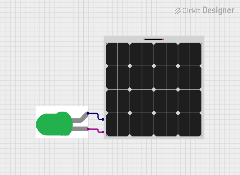 Open Project in Cirkit Designer
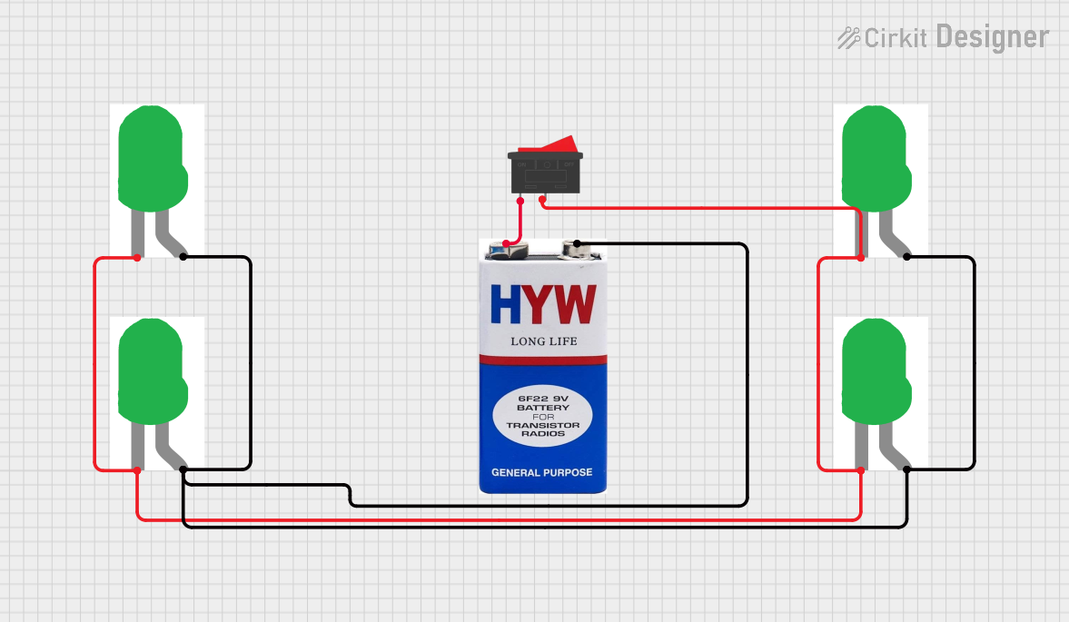 Open Project in Cirkit Designer
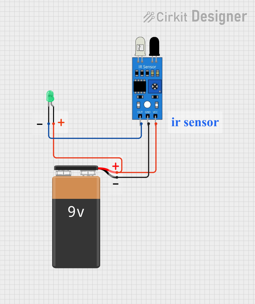 Open Project in Cirkit Designer
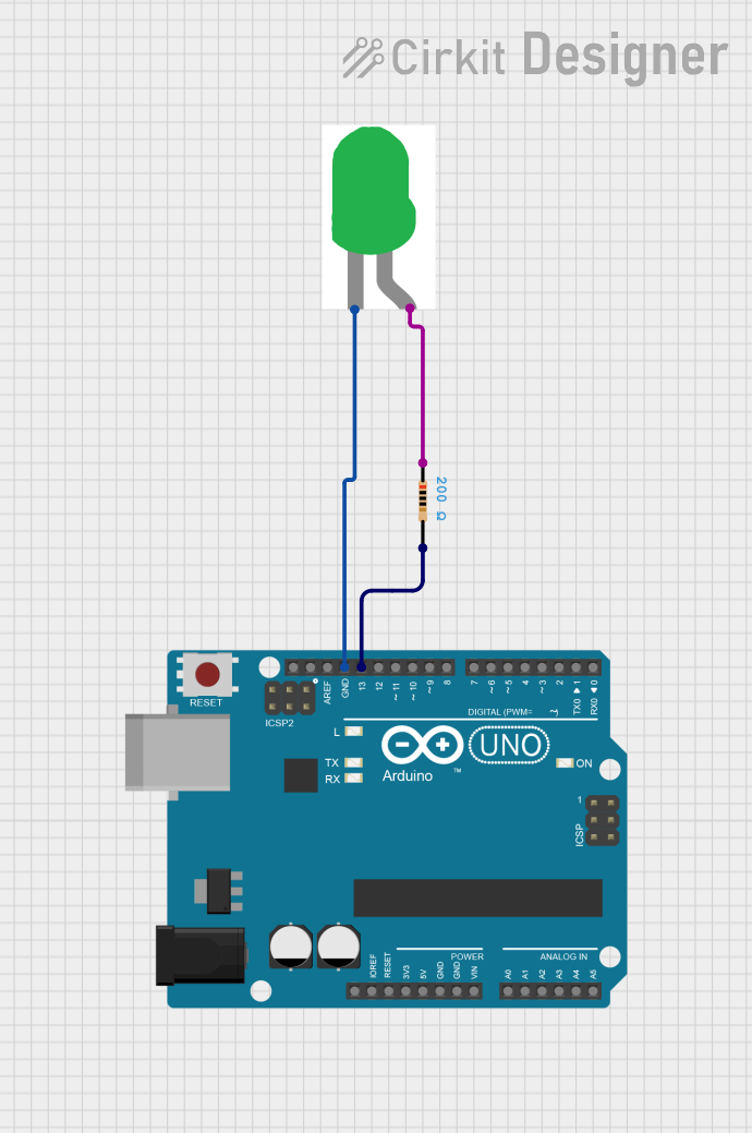 Open Project in Cirkit Designer
Explore Projects Built with Green LED
Open Project in Cirkit DesignerOpen Project in Cirkit DesignerOpen Project in Cirkit DesignerOpen Project in Cirkit DesignerCommon Applications and Use Cases
- Power and status indicators in electronic devices
- Signal lights in control panels
- Decorative lighting and displays
- Visual feedback in embedded systems
- Educational and hobbyist projects
Technical Specifications
Below are the typical specifications for a standard Green LED. Note that actual values may vary slightly depending on the manufacturer.
| Parameter | Value |
|---|---|
| Forward Voltage (Vf) | 2.0V to 3.2V |
| Forward Current (If) | 10mA to 20mA |
| Maximum Reverse Voltage | 5V |
| Power Dissipation | 60mW |
| Wavelength | 520nm to 570nm (green light) |
| Viewing Angle | 20° to 60° |
| Operating Temperature | -40°C to +85°C |
Pin Configuration and Descriptions
Green LEDs typically have two pins: the anode (positive) and the cathode (negative). The cathode is usually shorter and may have a flat edge on the LED casing for identification.
| Pin | Name | Description |
|---|---|---|
| 1 | Anode (+) | Connect to the positive terminal of the power supply |
| 2 | Cathode (-) | Connect to the negative terminal or ground |
Usage Instructions
How to Use the Green LED in a Circuit
Determine the Resistor Value: To prevent damage, always use a current-limiting resistor in series with the LED. Calculate the resistor value using Ohm's Law: [ R = \frac{V_{supply} - V_f}{I_f} ] Where:
- (V_{supply}) is the supply voltage
- (V_f) is the forward voltage of the LED
- (I_f) is the desired forward current (e.g., 10mA)
Connect the LED:
- Connect the anode to the positive terminal of the power supply through the resistor.
- Connect the cathode to the ground.
Test the Circuit: Power the circuit and observe the green light emitted by the LED.
Important Considerations and Best Practices
- Polarity Matters: LEDs are polarized components. Reversing the polarity may damage the LED.
- Avoid Overcurrent: Exceeding the maximum forward current can permanently damage the LED.
- Use Proper Resistors: Always calculate and use an appropriate resistor to limit current.
- Heat Management: While LEDs generate minimal heat, ensure proper ventilation in high-power applications.
Example: Connecting a Green LED to an Arduino UNO
Below is an example of how to connect and control a Green LED using an Arduino UNO.
Circuit Setup
- Connect the anode of the Green LED to digital pin 9 on the Arduino through a 220Ω resistor.
- Connect the cathode to the Arduino's GND pin.
Arduino Code
// Green LED Blink Example
// This code blinks a Green LED connected to pin 9 of the Arduino UNO.

const int ledPin = 9; // Define the pin connected to the LED

void setup() {
  pinMode(ledPin, OUTPUT); // Set the LED pin as an output
}

void loop() {
  digitalWrite(ledPin, HIGH); // Turn the LED on
  delay(1000);               // Wait for 1 second
  digitalWrite(ledPin, LOW);  // Turn the LED off
  delay(1000);               // Wait for 1 second
}
Troubleshooting and FAQs
Common Issues and Solutions
LED Does Not Light Up:
Cause: Incorrect polarity.
Solution: Ensure the anode is connected to the positive terminal and the cathode to ground.
Cause: No current-limiting resistor or incorrect resistor value.
Solution: Verify the resistor value and connections.
LED is Dim:
- Cause: Insufficient current.
- Solution: Check the resistor value and ensure it allows enough current (e.g., 10mA).
LED Burns Out Quickly:
- Cause: Excessive current.
- Solution: Use a proper current-limiting resistor to prevent overcurrent.
LED Flickers:
- Cause: Unstable power supply or loose connections.
- Solution: Check the power source and ensure all connections are secure.
FAQs
Q: Can I connect a Green LED directly to a 5V power supply?
A: No, you must use a current-limiting resistor to prevent damage to the LED.Q: How do I identify the anode and cathode of the LED?
A: The anode is the longer pin, and the cathode is the shorter pin. The cathode side may also have a flat edge on the LED casing.Q: Can I use a Green LED with a 3.3V microcontroller?
A: Yes, but ensure you calculate the appropriate resistor value for the 3.3V supply.Q: What happens if I exceed the maximum forward current?
A: Exceeding the maximum forward current can permanently damage the LED.
By following this documentation, you can effectively use a Green LED in your electronic projects.