How to Use MP-1584: Examples, Pinouts, and Specs
Introduction
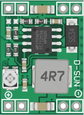
The MP-1584 is a high-efficiency step-down (buck) voltage regulator capable of delivering up to 3A of output current. It is designed to convert a higher input voltage into a stable, lower output voltage with high efficiency. The MP-1584 features a wide input voltage range (4.5V to 28V), adjustable output voltage (0.8V to 20V), and built-in protection mechanisms such as overcurrent protection and thermal shutdown. These features make it a versatile and reliable choice for power management in various electronic applications.
Explore Projects Built with MP-1584
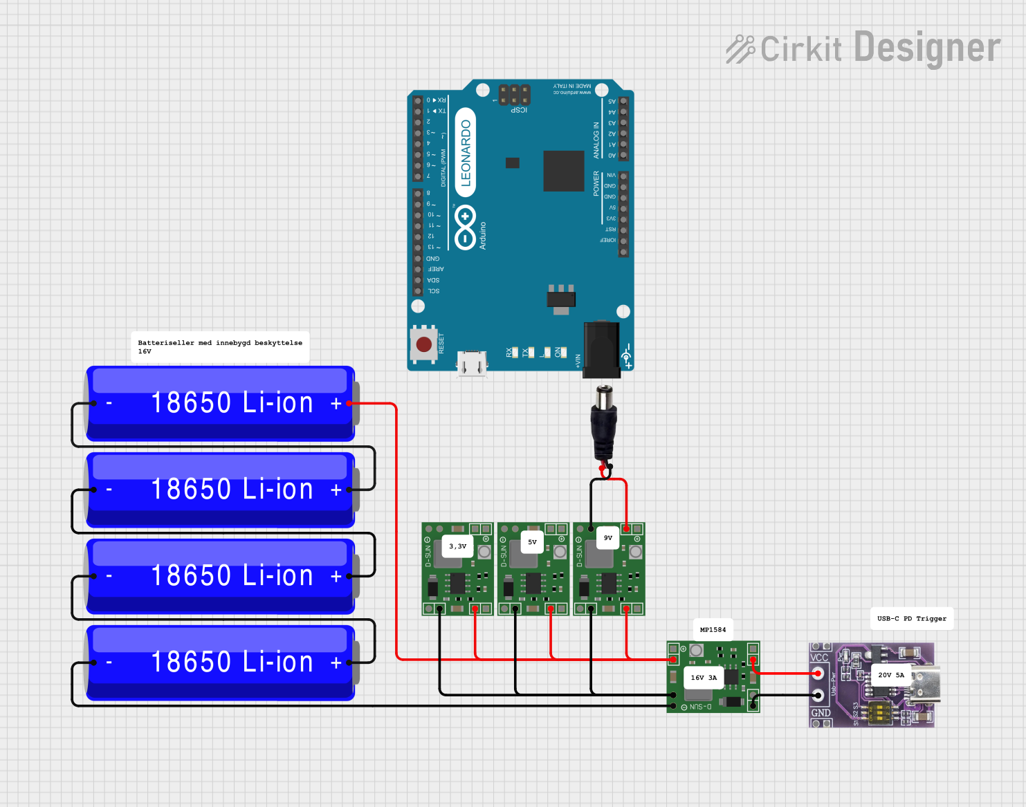

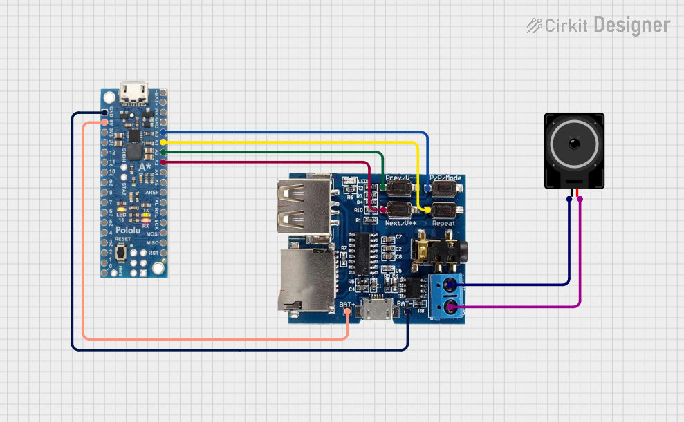
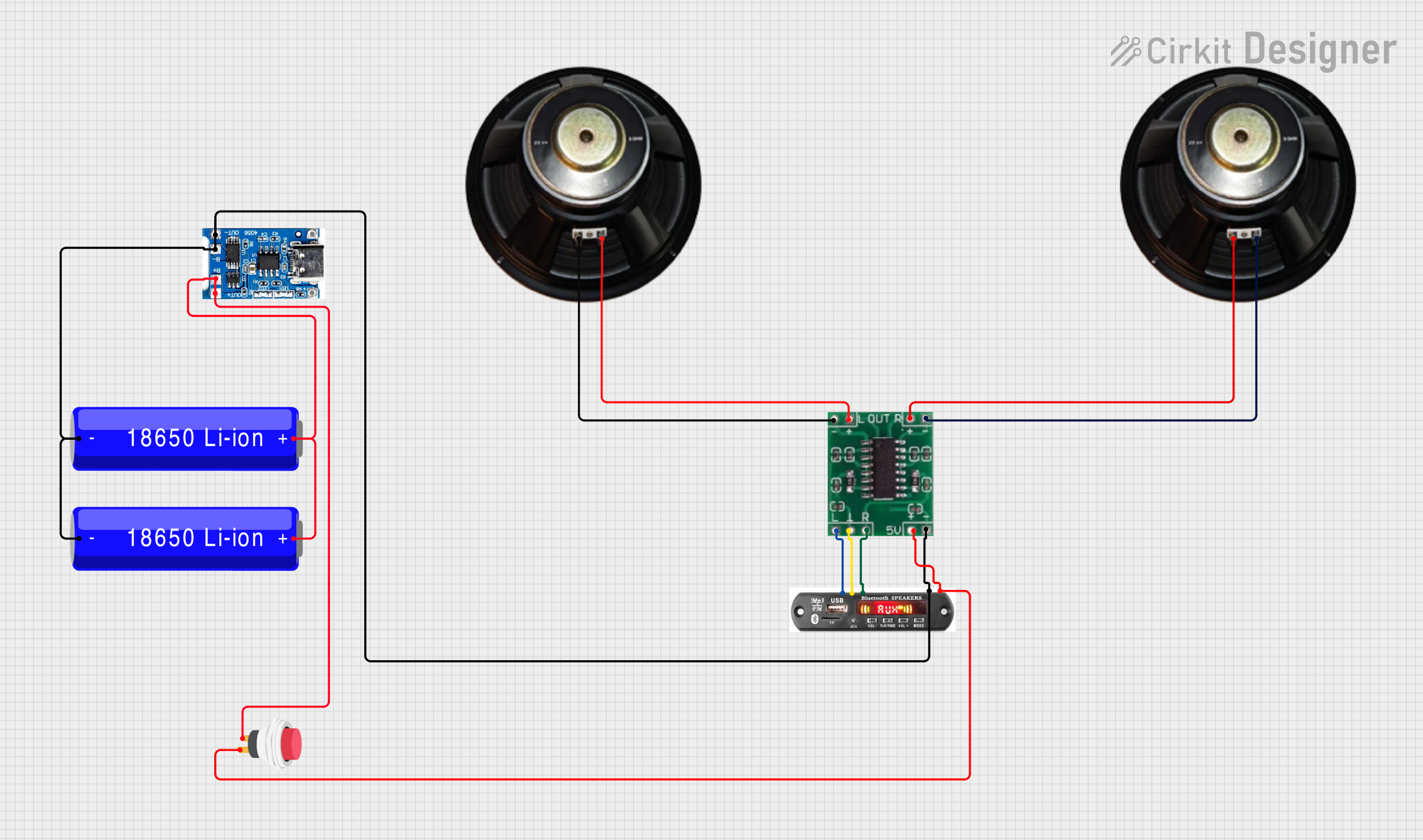
Explore Projects Built with MP-1584
Common Applications
- Powering microcontrollers, sensors, and other low-voltage devices
- Battery-powered systems
- DC-DC conversion in embedded systems
- LED drivers
- Industrial and consumer electronics
Technical Specifications
Key Specifications
| Parameter | Value |
|---|---|
| Input Voltage Range | 4.5V to 28V |
| Output Voltage Range | 0.8V to 20V (adjustable) |
| Maximum Output Current | 3A |
| Efficiency | Up to 96% |
| Switching Frequency | 340 kHz |
| Output Voltage Ripple | <30 mV (typical) |
| Operating Temperature | -40°C to +85°C |
| Protection Features | Overcurrent, thermal shutdown |
Pin Configuration and Descriptions
The MP-1584 is typically available as a small module with the following pinout:
| Pin Name | Description |
|---|---|
| VIN | Input voltage pin. Connect to the positive terminal of the input power source. |
| GND | Ground pin. Connect to the negative terminal of the input power source. |
| VOUT | Output voltage pin. Provides the regulated output voltage. |
| EN | Enable pin. Used to enable or disable the module. Connect to VIN for always-on operation. |
| ADJ | Adjustment pin. Connect a resistor divider to set the output voltage. |
Usage Instructions
How to Use the MP-1584 in a Circuit
- Input Voltage Connection: Connect the input voltage source (4.5V to 28V) to the
VINpin and ground to theGNDpin. - Output Voltage Adjustment: Use a resistor divider network connected to the
ADJpin to set the desired output voltage. The formula for calculating the output voltage is: [ V_{OUT} = V_{REF} \times \left(1 + \frac{R1}{R2}\right) ] where ( V_{REF} ) is 0.8V, ( R1 ) is the resistor betweenVOUTandADJ, and ( R2 ) is the resistor betweenADJand ground. - Output Connection: Connect the load to the
VOUTpin and ground. - Enable Pin: If you want the module to always be on, connect the
ENpin toVIN. Otherwise, use a microcontroller or switch to control the enable pin.
Important Considerations
- Input Voltage: Ensure the input voltage is within the specified range (4.5V to 28V) and is higher than the desired output voltage.
- Heat Dissipation: For high current loads, the module may generate heat. Use proper heat dissipation techniques, such as adding a heatsink or ensuring adequate airflow.
- Capacitors: Use appropriate input and output capacitors to reduce voltage ripple and improve stability. Typical values are 22µF for input and 47µF for output.
- Load Current: Do not exceed the maximum output current of 3A to avoid triggering overcurrent protection.
Example: Using MP-1584 with Arduino UNO
The MP-1584 can be used to power an Arduino UNO by stepping down a 12V input to 5V. Below is an example circuit and Arduino code to control the EN pin.
Circuit Setup
- Connect a 12V power source to the
VINandGNDpins of the MP-1584. - Adjust the output voltage to 5V using the resistor divider or onboard potentiometer.
- Connect the
VOUTpin to the 5V pin of the Arduino UNO andGNDto the Arduino's ground. - Connect the
ENpin to a digital pin on the Arduino (e.g., pin 7).
Arduino Code
// Example code to control the MP-1584 enable pin using Arduino UNO

const int enablePin = 7; // Pin connected to the EN pin of MP-1584

void setup() {
  pinMode(enablePin, OUTPUT); // Set the enable pin as an output
  digitalWrite(enablePin, HIGH); // Enable the MP-1584 module
}

void loop() {
  // Example: Toggle the MP-1584 module on and off every 5 seconds
  digitalWrite(enablePin, HIGH); // Enable the module
  delay(5000); // Wait for 5 seconds
  digitalWrite(enablePin, LOW); // Disable the module
  delay(5000); // Wait for 5 seconds
}
Troubleshooting and FAQs
Common Issues and Solutions
No Output Voltage
- Cause: The
ENpin is not connected or is set to a low state. - Solution: Ensure the
ENpin is connected toVINor a high logic level.
- Cause: The
Output Voltage is Incorrect
- Cause: Incorrect resistor values in the voltage divider.
- Solution: Recalculate and verify the resistor values using the output voltage formula.
Module Overheating
- Cause: Excessive load current or insufficient heat dissipation.
- Solution: Reduce the load current or improve cooling (e.g., add a heatsink).
High Output Voltage Ripple
- Cause: Insufficient input or output capacitance.
- Solution: Add or replace capacitors with appropriate values (e.g., 22µF for input, 47µF for output).
Module Not Working
- Cause: Input voltage is outside the specified range.
- Solution: Verify that the input voltage is between 4.5V and 28V.
FAQs
Can the MP-1584 be used with a battery? Yes, the MP-1584 can step down the voltage from a battery as long as the input voltage is within the specified range.
What is the maximum efficiency of the MP-1584? The MP-1584 can achieve up to 96% efficiency under optimal conditions.
Can I use the MP-1584 to power a Raspberry Pi? Yes, but ensure the output voltage is set to 5V and the current demand does not exceed 3A.
Is the MP-1584 suitable for automotive applications? Yes, as long as the input voltage is regulated and within the specified range.