Cirkit Designer Logo
Cirkit Designer
Your all-in-one circuit design IDE
Home / 
Component Documentation

How to Use Adafruit DS1841: Examples, Pinouts, and Specs

Image of Adafruit DS1841
Cirkit Designer LogoDesign with Adafruit DS1841 in Cirkit Designer

Introduction

The Adafruit DS1841 is a versatile digital potentiometer module that provides an electronic method of adjusting resistance in a circuit. This component is particularly useful in applications where precise and repeatable adjustments are required, such as volume control in audio systems, brightness control in lighting systems, and tuning in analog circuits. The DS1841 can be controlled via a digital interface, making it an excellent choice for integration with microcontrollers like the Arduino UNO.

Explore Projects Built with Adafruit DS1841

Use Cirkit Designer to design, explore, and prototype these projects online. Some projects support real-time simulation. Click "Open Project" to start designing instantly!
Arduino Mega 2560 and Adafruit DS1841 Battery-Powered Sensor Interface
Image of Capacitance meter: A project utilizing Adafruit DS1841 in a practical application
This circuit is a sensor interface system powered by a 9V battery, featuring an Arduino Mega 2560 microcontroller and an Adafruit DS1841 digital potentiometer. The circuit includes resistors and capacitors for signal conditioning, with the Arduino handling data acquisition and communication via I2C with the DS1841.
Cirkit Designer LogoOpen Project in Cirkit Designer
ESP32-Based Weather Station with BME280 and DS18B20 Sensors, Battery-Powered and Wi-Fi Enabled
Image of Copy of Circuit Diagram Proto: A project utilizing Adafruit DS1841 in a practical application
This circuit is a weather monitoring system that uses an ESP32 microcontroller to read temperature data from a DS18B20 sensor and pressure data from a BME280 sensor. The data is displayed on a 20x4 I2C LCD panel, and the system can communicate via a SIM800L module. A piezo buzzer is included for audible alerts, and the entire system is powered by a 5V battery.
Cirkit Designer LogoOpen Project in Cirkit Designer
Arduino Mega 2560-Based Multi-Sensor Weather Station with TFT Display and IR Control
Image of aqua2: A project utilizing Adafruit DS1841 in a practical application
This circuit uses an Arduino Mega 2560 to read temperature data from multiple DS18B20 sensors, display the data on an ILI9341 TFT display, and maintain time using an Adafruit DS1307 RTC module. It also receives IR signals using a VS1838B IR receiver and includes an Adafruit MS8607 PHT sensor for additional environmental monitoring.
Cirkit Designer LogoOpen Project in Cirkit Designer
Arduino UNO with NRF24L01 Wireless Communication and DHT11 Temperature Sensing
Image of WSN 1: A project utilizing Adafruit DS1841 in a practical application
This circuit connects an Arduino UNO with an NRF24L01 Adapter and a DHT11 temperature and humidity sensor. The Arduino provides power and ground to both the NRF24L01 Adapter and the DHT11 sensor, and it is configured to communicate with the NRF24L01 Adapter using SPI (with pins D13 for SCK, D12 for MISO, D11 for MOSI, D10 for CSN, and D9 for CE). Additionally, the DHT11 sensor's data pin is connected to the Arduino's D2 pin for digital signal reading.
Cirkit Designer LogoOpen Project in Cirkit Designer

Explore Projects Built with Adafruit DS1841

Use Cirkit Designer to design, explore, and prototype these projects online. Some projects support real-time simulation. Click "Open Project" to start designing instantly!
Image of Capacitance meter: A project utilizing Adafruit DS1841 in a practical application
Arduino Mega 2560 and Adafruit DS1841 Battery-Powered Sensor Interface
This circuit is a sensor interface system powered by a 9V battery, featuring an Arduino Mega 2560 microcontroller and an Adafruit DS1841 digital potentiometer. The circuit includes resistors and capacitors for signal conditioning, with the Arduino handling data acquisition and communication via I2C with the DS1841.
Cirkit Designer LogoOpen Project in Cirkit Designer
Image of Copy of Circuit Diagram Proto: A project utilizing Adafruit DS1841 in a practical application
ESP32-Based Weather Station with BME280 and DS18B20 Sensors, Battery-Powered and Wi-Fi Enabled
This circuit is a weather monitoring system that uses an ESP32 microcontroller to read temperature data from a DS18B20 sensor and pressure data from a BME280 sensor. The data is displayed on a 20x4 I2C LCD panel, and the system can communicate via a SIM800L module. A piezo buzzer is included for audible alerts, and the entire system is powered by a 5V battery.
Cirkit Designer LogoOpen Project in Cirkit Designer
Image of aqua2: A project utilizing Adafruit DS1841 in a practical application
Arduino Mega 2560-Based Multi-Sensor Weather Station with TFT Display and IR Control
This circuit uses an Arduino Mega 2560 to read temperature data from multiple DS18B20 sensors, display the data on an ILI9341 TFT display, and maintain time using an Adafruit DS1307 RTC module. It also receives IR signals using a VS1838B IR receiver and includes an Adafruit MS8607 PHT sensor for additional environmental monitoring.
Cirkit Designer LogoOpen Project in Cirkit Designer
Image of WSN 1: A project utilizing Adafruit DS1841 in a practical application
Arduino UNO with NRF24L01 Wireless Communication and DHT11 Temperature Sensing
This circuit connects an Arduino UNO with an NRF24L01 Adapter and a DHT11 temperature and humidity sensor. The Arduino provides power and ground to both the NRF24L01 Adapter and the DHT11 sensor, and it is configured to communicate with the NRF24L01 Adapter using SPI (with pins D13 for SCK, D12 for MISO, D11 for MOSI, D10 for CSN, and D9 for CE). Additionally, the DHT11 sensor's data pin is connected to the Arduino's D2 pin for digital signal reading.
Cirkit Designer LogoOpen Project in Cirkit Designer

Technical Specifications

Key Technical Details

  • Resistance Range: 10kΩ to 100kΩ (configurable)
  • Interface: I2C
  • Resolution: 256 positions
  • Operating Voltage: 2.7V to 5.5V
  • Temperature Range: -40°C to +85°C
  • Package: SOT-23-6

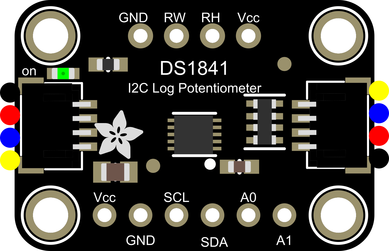
Pin Configuration and Descriptions

Pin Number Name Description
1 A Potentiometer terminal A (high side)
2 W Wiper terminal (variable output)
3 GND Ground terminal
4 SDA I2C Data line
5 SCL I2C Clock line
6 B Potentiometer terminal B (low side)

Usage Instructions

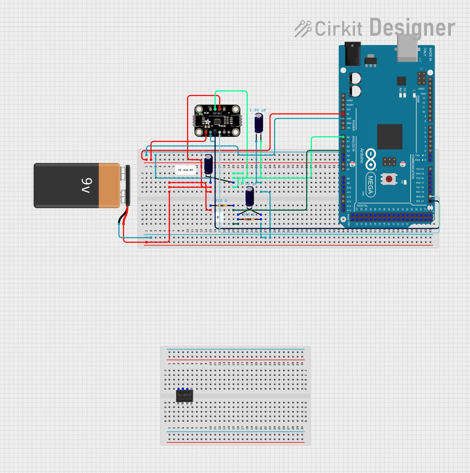
Integration with a Circuit

To use the DS1841 in a circuit, connect the A and B pins to the circuit points where you want to insert a variable resistor. The W pin will act as the wiper, which adjusts the resistance between A and W. Connect the SDA and SCL pins to the corresponding I2C data and clock lines on your microcontroller.

Best Practices

  • Ensure that the power supply voltage is within the specified operating range.
  • Connect a pull-up resistor (typically 4.7kΩ to 10kΩ) to the SDA and SCL lines if your microcontroller does not have built-in pull-ups.
  • Avoid applying a voltage to the A, B, or W terminals that exceeds the power supply voltage.
  • Use proper decoupling capacitors close to the power supply pins to minimize noise.

Example Code for Arduino UNO

#include <Wire.h>

// DS1841 I2C address
#define DS1841_ADDR 0x28

// Function to set the wiper position
void setWiper(uint8_t position) {
  Wire.beginTransmission(DS1841_ADDR);
  Wire.write(0xA9); // Command byte for wiper position
  Wire.write(position); // Wiper position (0-255)
  Wire.endTransmission();
}

void setup() {
  Wire.begin(); // Initialize I2C
  Serial.begin(9600); // Start serial communication for debugging
}

void loop() {
  // Example: Set the wiper to the middle position
  setWiper(128);
  Serial.println("Wiper set to middle position.");
  delay(2000); // Wait for 2 seconds
}

Troubleshooting and FAQs

Common Issues

  • I2C Communication Failure: Ensure that the SDA and SCL lines are connected correctly and that pull-up resistors are in place.
  • Unexpected Resistance Values: Verify that the wiper position is set correctly and that the DS1841 is not damaged.

Solutions and Tips

  • If you encounter communication issues, use an I2C scanner sketch to check if the DS1841 is detected on the I2C bus.
  • Always handle the DS1841 with proper ESD precautions to prevent damage to the device.

FAQs

Q: Can the DS1841 be used with voltages higher than 5.5V? A: No, applying a voltage higher than 5.5V can damage the device.

Q: How many DS1841 devices can be connected on the same I2C bus? A: Multiple devices can be connected if they have different I2C addresses. Check the datasheet for address configuration options.

Q: Is the DS1841 volatile or non-volatile? A: The DS1841 is a volatile digital potentiometer, meaning it will lose its set resistance value when power is removed.

For further assistance or more advanced troubleshooting, consult the Adafruit DS1841 datasheet or contact technical support.