How to Use SparkFun Blackberry Trackballer Breakout: Examples, Pinouts, and Specs
Introduction
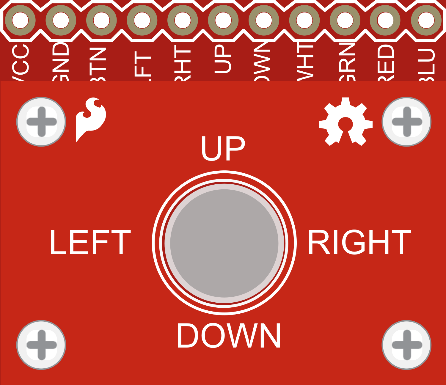
The SparkFun Blackberry Trackballer Breakout is an innovative interface component that allows users to integrate a trackball input device, similar to those found in Blackberry phones, into their electronic projects. This breakout board is particularly useful for adding intuitive navigation controls to embedded systems. Common applications include DIY game controllers, menu navigation for small displays, and robotic control interfaces.
Explore Projects Built with SparkFun Blackberry Trackballer Breakout

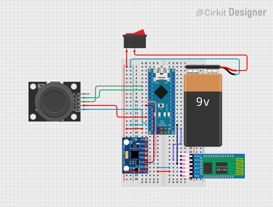
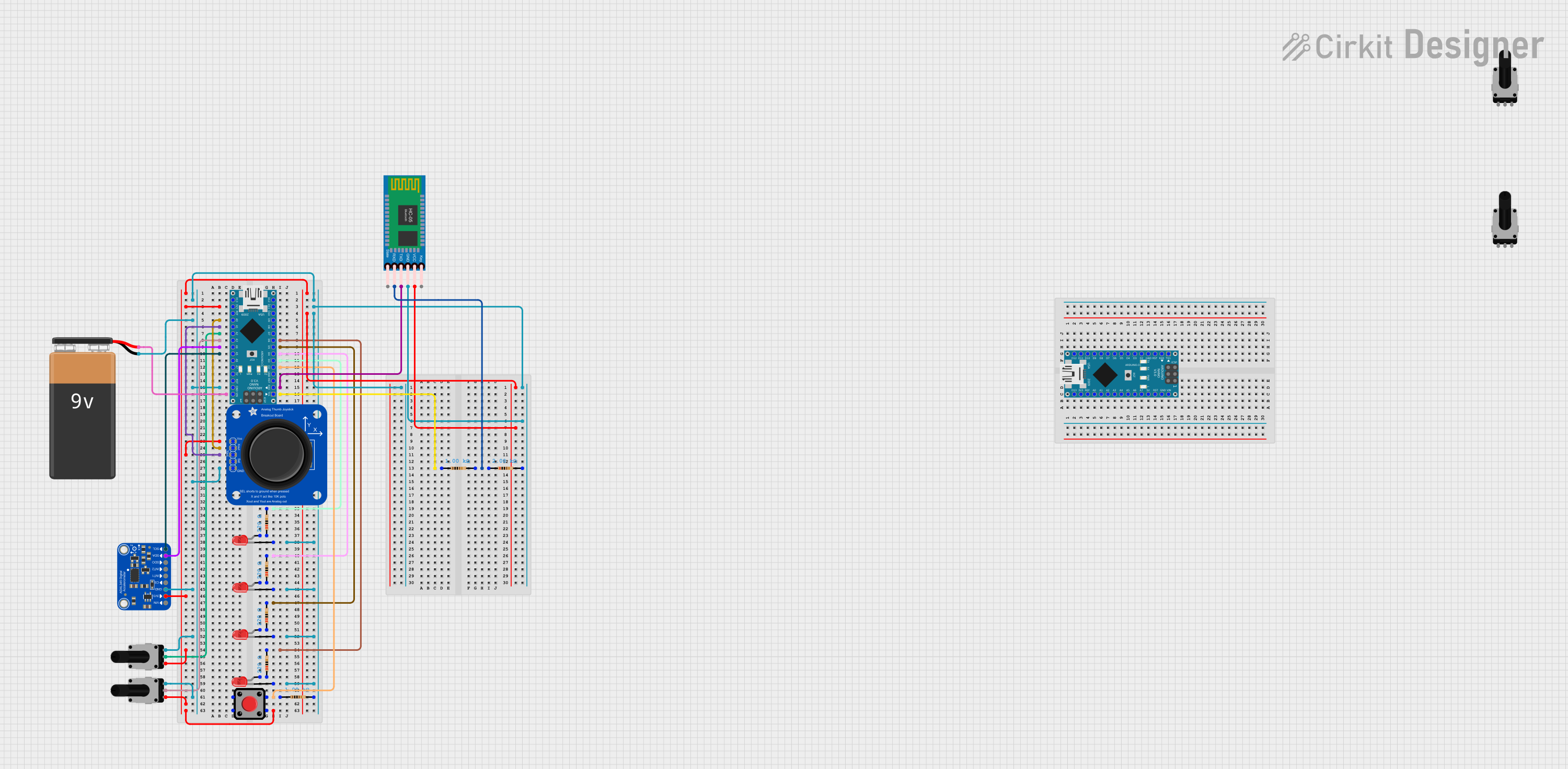

Explore Projects Built with SparkFun Blackberry Trackballer Breakout
Technical Specifications
Key Technical Details
- Voltage: 2.5V to 5.25V
- Current: 15mA (typical use)
- Output: Quadrature for the X and Y movement, plus select signal
- Interface: Digital I/O compatible
Pin Configuration and Descriptions
| Pin Number | Name | Description |
|---|---|---|
| 1 | GND | Ground connection |
| 2 | VCC | Power supply (2.5V to 5.25V) |
| 3 | TBX | Trackball X-axis movement output |
| 4 | TBY | Trackball Y-axis movement output |
| 5 | TBS | Trackball select button output |
| 6 | LEDA | Anode for the four LEDs |
| 7 | LEDK1 | Cathode for LED 1 |
| 8 | LEDK2 | Cathode for LED 2 |
| 9 | LEDK3 | Cathode for LED 3 |
| 10 | LEDK4 | Cathode for LED 4 |
Usage Instructions
Interfacing with a Microcontroller
To use the SparkFun Blackberry Trackballer Breakout with a microcontroller, such as an Arduino UNO, follow these steps:
- Connect the VCC pin to the 5V output on the Arduino.
- Connect the GND pin to one of the GND pins on the Arduino.
- Connect the TBX, TBY, and TBS pins to digital I/O pins on the Arduino.
- Optionally, connect the LEDA to 5V and each LEDK pin to a digital pin through a current-limiting resistor to control the trackball's backlight LEDs.
Example Arduino Code
// Define the pin connections
const int pinTBX = 2; // Trackball X-axis
const int pinTBY = 3; // Trackball Y-axis
const int pinTBS = 4; // Trackball select button

void setup() {
  pinMode(pinTBX, INPUT);
  pinMode(pinTBY, INPUT);
  pinMode(pinTBS, INPUT);
  Serial.begin(9600);
}

void loop() {
  // Read the trackball movement and button state
  int xValue = digitalRead(pinTBX);
  int yValue = digitalRead(pinTBY);
  int buttonState = digitalRead(pinTBS);

  // Print the values to the serial monitor
  Serial.print("X: ");
  Serial.print(xValue);
  Serial.print(" Y: ");
  Serial.print(yValue);
  Serial.print(" Button: ");
  Serial.println(buttonState);

  delay(100); // Small delay to debounce and reduce serial output rate
}
Important Considerations and Best Practices
- Ensure that the voltage supplied to the VCC pin does not exceed 5.25V to prevent damage.
- Use pull-up or pull-down resistors on the TBX, TBY, and TBS pins if your microcontroller requires them.
- Debounce the button input in software to prevent false triggering.
- When controlling the backlight LEDs, use appropriate current-limiting resistors to prevent LED damage.
Troubleshooting and FAQs
Common Issues
- Trackball not responding: Ensure that all connections are secure and that the microcontroller pins are correctly configured as inputs.
- LEDs not lighting up: Check the LED connections and ensure that current-limiting resistors are in place. Verify that the LEDA pin is supplied with power.
Solutions and Tips for Troubleshooting
- Double-check wiring against the pin configuration table.
- Use a multimeter to verify that the VCC and GND connections are supplying the correct voltage.
- If using the Arduino's internal pull-up resistors, activate them with
pinMode(pin, INPUT_PULLUP);in the setup function.
FAQs
Q: Can I use this breakout with a 3.3V system? A: Yes, the trackball can operate at voltages as low as 2.5V.
Q: How do I interpret the quadrature output for X and Y movements? A: The TBX and TBY pins will produce digital pulses as the trackball is moved. These pulses can be read using digital I/O and interpreted to determine the direction and magnitude of movement.
Q: Is it possible to control the brightness of the LEDs? A: Yes, by connecting the LED cathode pins to PWM-capable pins on your microcontroller, you can adjust the brightness using analog output commands.
For further assistance or inquiries, please contact SparkFun's technical support or visit the community forums.