How to Use 3 Position Switch: Examples, Pinouts, and Specs
Introduction
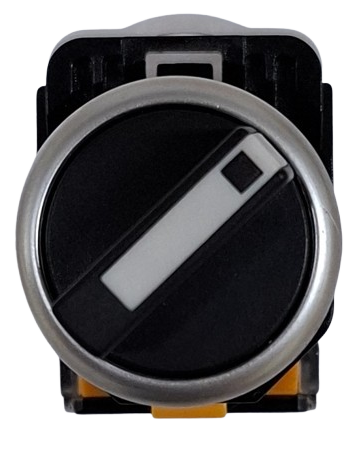
A 3 Position Switch is a versatile and simple component used in electronic circuits to control the flow of current between different paths. It allows the user to select one of three different modes or circuits by toggling the switch between three distinct positions. Common applications include selecting different operational modes in a device, changing input sources in audio equipment, or controlling various functions in a vehicle, such as lighting or wiper speed.
Explore Projects Built with 3 Position Switch

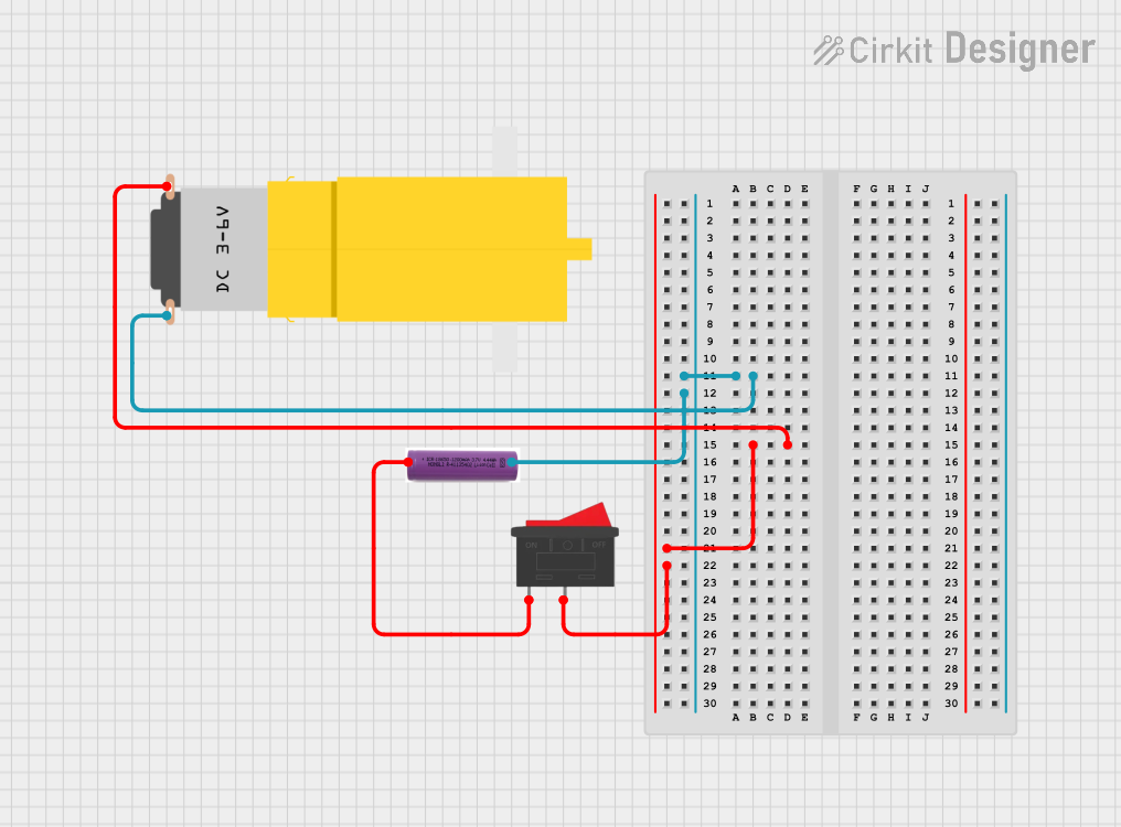
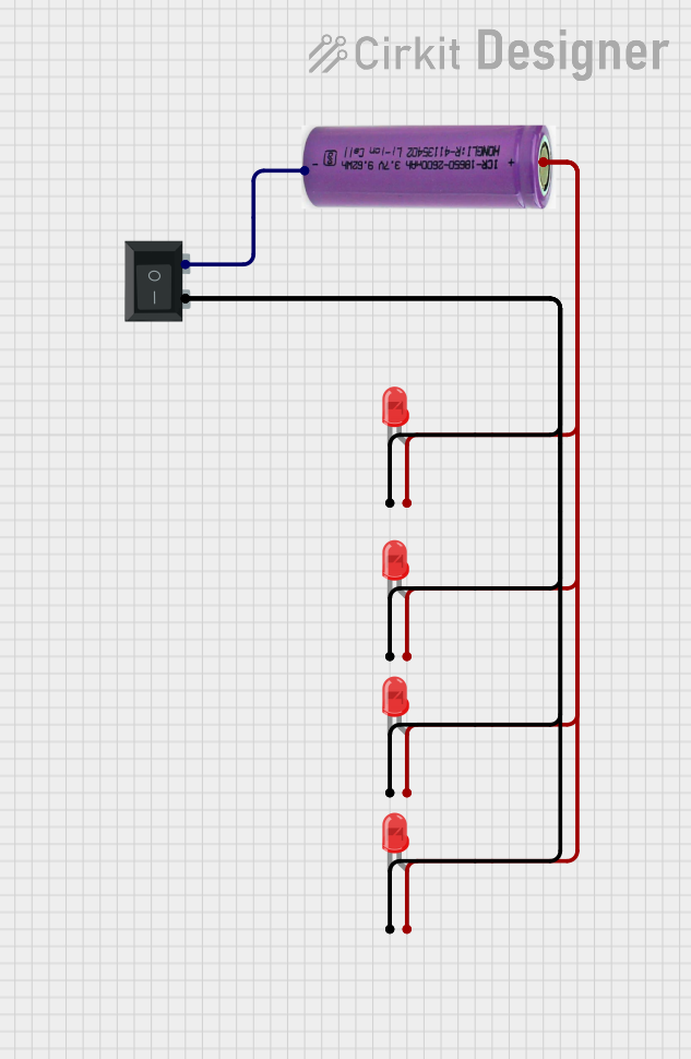

Explore Projects Built with 3 Position Switch
Technical Specifications
General Characteristics
- Switch Type: SP3T (Single Pole, Triple Throw)
- Contact Rating: Typically 5A at 120V AC or 28V DC (varies by model)
- Mechanical Life: Often rated for 30,000 to 50,000 cycles
- Operating Temperature Range: -20°C to 85°C (varies by model)
Pin Configuration and Descriptions
| Pin Number | Description | Notes |
|---|---|---|
| 1 | Common Pole | Connects to the shared terminal |
| 2 | Position 1 Output | Output for position 1 |
| 3 | Position 2 Output | Output for position 2 |
| 4 | Position 3 Output | Output for position 3 |
Note: The actual pin numbering may vary depending on the manufacturer. Always refer to the manufacturer's datasheet for exact details.
Usage Instructions
Integration into a Circuit
Identify the Common Pole: Determine which pin is the common pole (usually marked on the switch or in the datasheet).
Connect Outputs: Connect each of the output pins to the respective parts of the circuit that you wish to control.
Power Supply: Ensure that the power supply voltage and current do not exceed the switch's ratings.
Mounting: Secure the switch to your project's enclosure, if applicable, ensuring that it is easily accessible for operation.
Best Practices
- Use a pull-down or pull-up resistor on the output lines to ensure a defined logic level when the switch is in the off position.
- Avoid applying excessive force to the switch to prevent mechanical damage.
- Consider the environmental conditions where the switch will be used and ensure it meets the necessary specifications.
Example Code for Arduino UNO
This example demonstrates how to use a 3 Position Switch with an Arduino UNO to control three LEDs.
// Define the Arduino pins connected to the switch positions
const int switchPin1 = 2;
const int switchPin2 = 3;
const int switchPin3 = 4;

// Define the Arduino pins connected to the LEDs
const int ledPin1 = 5;
const int ledPin2 = 6;
const int ledPin3 = 7;

void setup() {
  // Initialize the switch input pins
  pinMode(switchPin1, INPUT_PULLUP);
  pinMode(switchPin2, INPUT_PULLUP);
  pinMode(switchPin3, INPUT_PULLUP);

  // Initialize the LED output pins
  pinMode(ledPin1, OUTPUT);
  pinMode(ledPin2, OUTPUT);
  pinMode(ledPin3, OUTPUT);
}

void loop() {
  // Read the state of the switch positions
  int state1 = digitalRead(switchPin1);
  int state2 = digitalRead(switchPin2);
  int state3 = digitalRead(switchPin3);

  // Control the LEDs based on the switch position
  digitalWrite(ledPin1, !state1); // Invert state due to INPUT_PULLUP
  digitalWrite(ledPin2, !state2); // Invert state due to INPUT_PULLUP
  digitalWrite(ledPin3, !state3); // Invert state due to INPUT_PULLUP
}
Note: The INPUT_PULLUP mode is used to enable the internal pull-up resistors in the Arduino, which ensures a high state when the switch is open.
Troubleshooting and FAQs
Common Issues
- Switch Does Not Change Output: Ensure that the switch is properly connected and that there are no loose wires or bad solder joints.
- Intermittent Operation: Check for mechanical wear or debris that may be causing poor contact within the switch.
- Unexpected Behavior in Circuit: Verify that the switch's current and voltage ratings are not being exceeded.
FAQs
Q: Can I use the 3 Position Switch with higher voltages? A: No, you should not exceed the voltage rating specified by the manufacturer to avoid damage and safety hazards.
Q: How can I debounce the switch in my digital circuit? A: Implement a software debounce routine in your microcontroller code or use a hardware debounce circuit with capacitors and resistors.
Q: Is it possible to use the switch with AC loads? A: Yes, as long as the switch is rated for the appropriate AC voltage and current, it can be used with AC loads.
For further assistance, always refer to the manufacturer's datasheet and technical support resources.