How to Use TIP120 Hi-Current Darlington Transistor: Examples, Pinouts, and Specs
Introduction
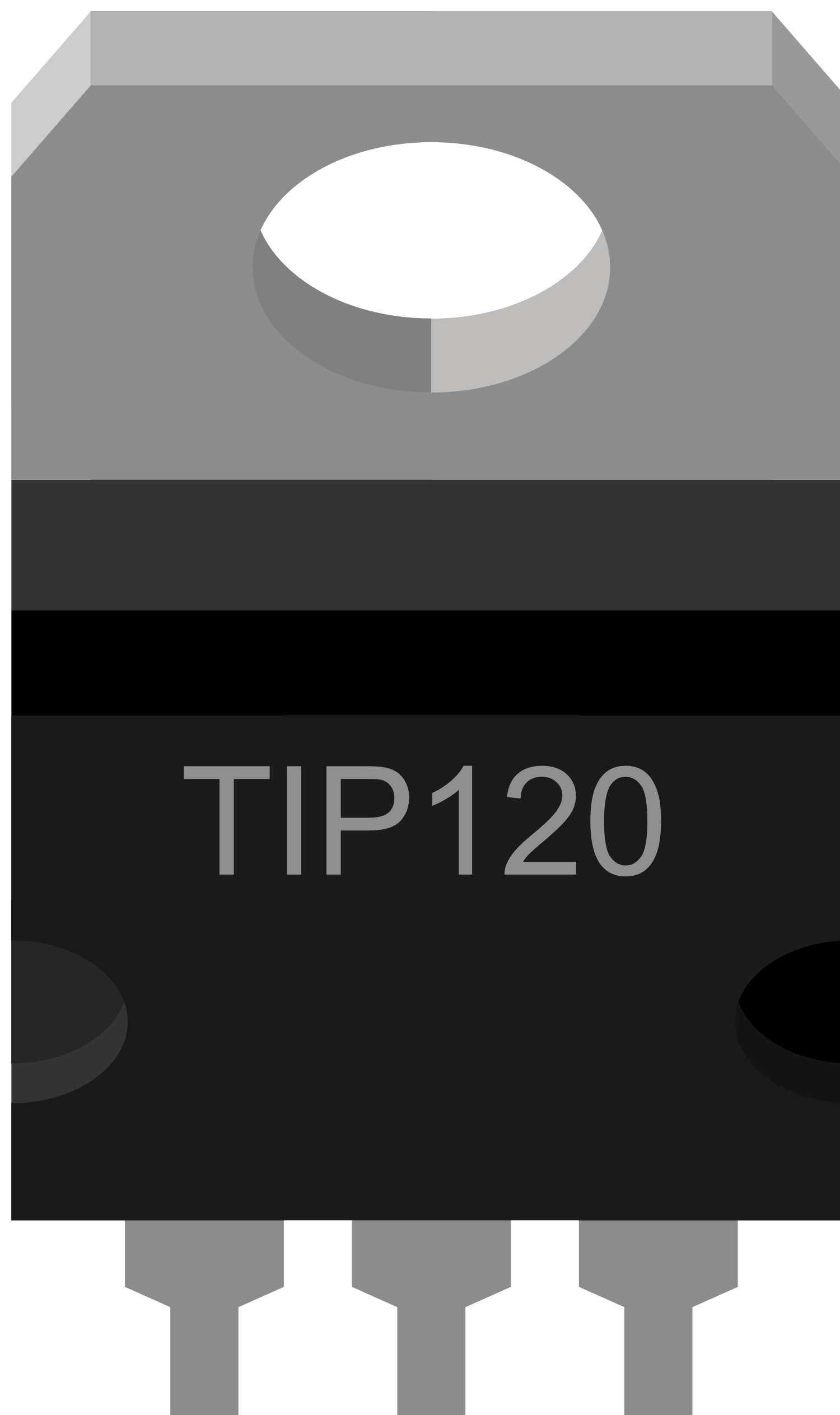
The TIP120 is a widely used NPN Darlington transistor capable of handling high current loads. It is designed for general-purpose amplifier and low-speed switching applications. The TIP120 is particularly useful for interfacing with microcontrollers, such as the Arduino UNO, to control devices like motors, solenoids, and relays that require more current than a microcontroller can provide directly.
Explore Projects Built with TIP120 Hi-Current Darlington Transistor
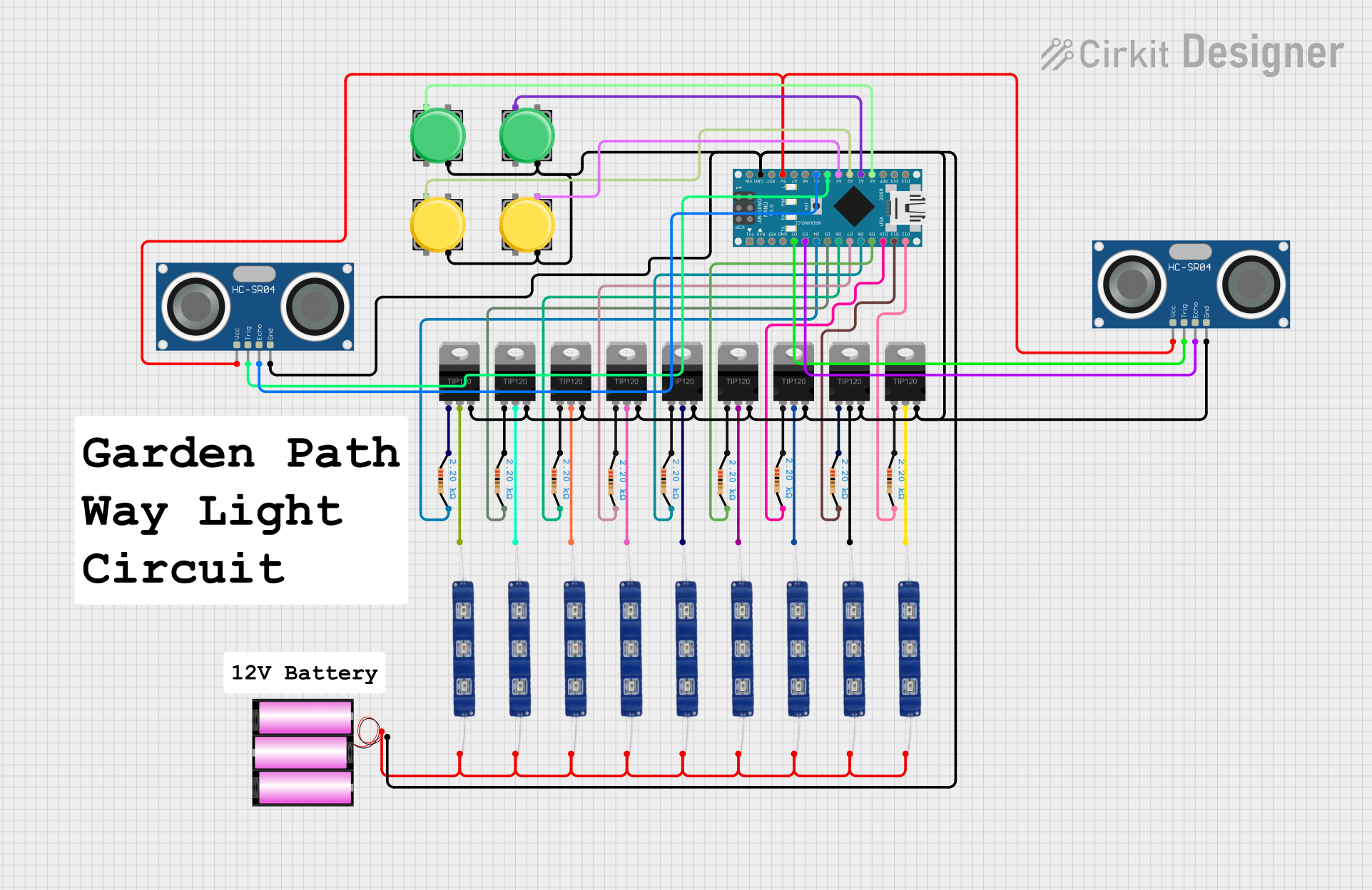
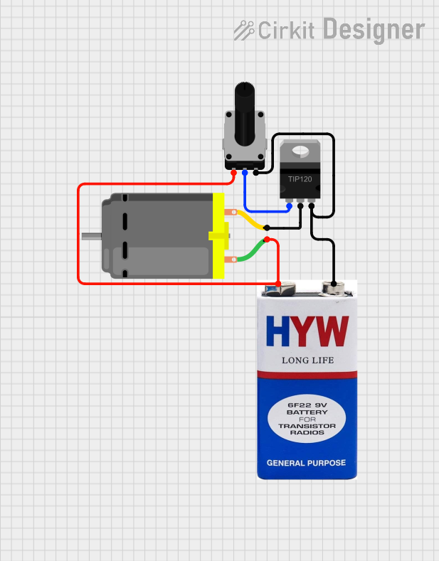
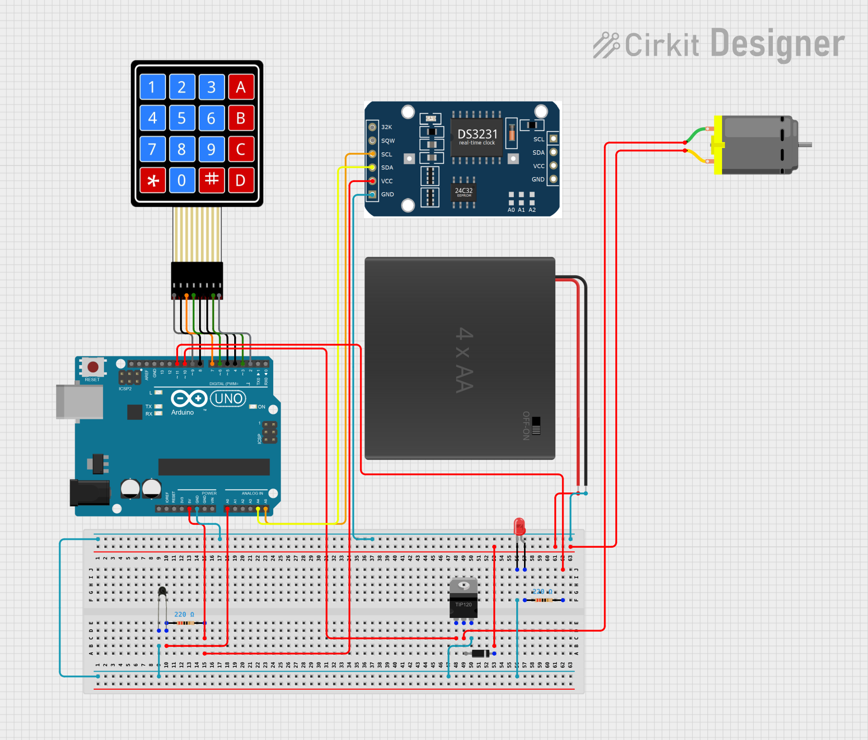
Explore Projects Built with TIP120 Hi-Current Darlington Transistor
Common Applications
- DC motor control
- Relay drivers
- Solenoid control
- LED light dimming
- Power regulators
Technical Specifications
Key Technical Details
- Collector-Emitter Voltage (Vce): 60V
- Collector-Base Voltage (Vcb): 60V
- Emitter-Base Voltage (Veb): 5V
- Collector Current (Ic): 5A (Continuous)
- Total Power Dissipation (Pd): 65W (at 25°C)
- DC Current Gain (hFE): 1000 (Minimum)
- Operating Junction Temperature (Tj): -65°C to +150°C
Pin Configuration and Descriptions
| Pin Number | Name | Description |
|---|---|---|
| 1 | Base | Control signal input, activates the transistor |
| 2 | Collector | Connected to the high-power load |
| 3 | Emitter | Connected to ground (common reference) |
Usage Instructions
How to Use the TIP120 in a Circuit
- Connect the base of the TIP120 to a digital output pin of a microcontroller through a current-limiting resistor (typically 1kΩ to 2.2kΩ).
- Connect the collector to the positive side of the load you wish to control.
- Connect the emitter to the ground of the power supply.
- Ensure the power supply voltage and current do not exceed the TIP120's maximum ratings.
Important Considerations and Best Practices
- Always use a base resistor to limit the current into the base of the transistor.
- Use a flyback diode across inductive loads (like motors and solenoids) to prevent back EMF damage.
- Consider heat sinking if operating near the maximum power dissipation limits.
- Ensure proper insulation and spacing on high-voltage or high-current circuits.
Example Code for Arduino UNO
// Define the pin connected to the base of the TIP120
const int controlPin = 3;

void setup() {
  // Set the control pin as an output
  pinMode(controlPin, OUTPUT);
}

void loop() {
  // Turn on the load connected to the TIP120
  digitalWrite(controlPin, HIGH);
  delay(1000); // Wait for 1 second

  // Turn off the load
  digitalWrite(controlPin, LOW);
  delay(1000); // Wait for 1 second
}
Troubleshooting and FAQs
Common Issues
- Load does not activate: Check the base resistor and connections. Ensure the control signal is being sent from the microcontroller.
- Transistor overheating: Verify that the current and power dissipation are within limits. Consider adding a heat sink.
- Unexpected behavior in the load: Ensure a flyback diode is used with inductive loads.
Solutions and Tips
- Base Resistor Value: If the base resistor is too high, the transistor may not fully saturate. If it's too low, it could damage the microcontroller's output pin or the transistor's base.
- Heat Sinking: Attach a heat sink to the TIP120 if it gets too hot to touch, or if operating near its maximum ratings.
- Flyback Diode: Always use a flyback diode when controlling inductive loads to prevent voltage spikes that can damage the transistor.
FAQs
Q: Can I use the TIP120 to control an AC load? A: No, the TIP120 is designed for DC applications only.
Q: What is the function of the Darlington pair inside the TIP120? A: The Darlington pair configuration within the TIP120 allows for high current gain, enabling control of high-current loads with a very small base current.
Q: How do I choose the correct base resistor value? A: The base resistor value depends on the voltage of the control signal and the desired base current. Use Ohm's law (R = V/I) to calculate the appropriate resistor value, ensuring the base current does not exceed the microcontroller's maximum current rating for a pin.