How to Use USB Type-C Breakout Board: Examples, Pinouts, and Specs
Introduction
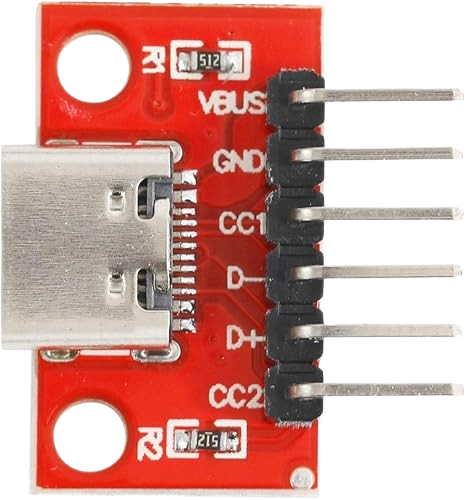
The Cermant Celent_CL533 USB Type-C Breakout Board is a compact and versatile tool designed to simplify prototyping and testing of USB Type-C connections. This breakout board provides easy access to the pins of a USB Type-C connector, enabling developers and engineers to experiment with USB Type-C functionalities such as power delivery, data transfer, and alternate modes.
Explore Projects Built with USB Type-C Breakout Board


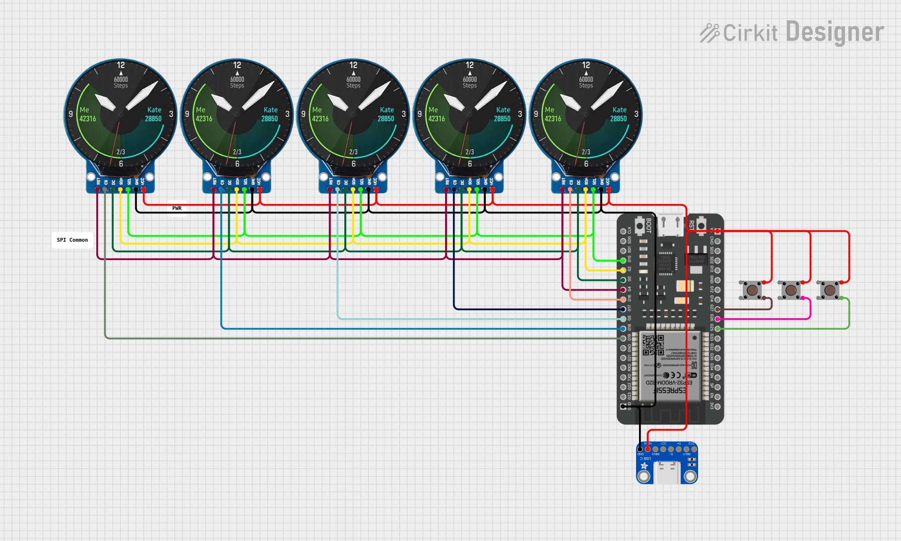
Explore Projects Built with USB Type-C Breakout Board
Common Applications and Use Cases
- Prototyping USB Type-C power delivery circuits
- Testing USB Type-C data transfer capabilities
- Developing USB Type-C-based devices
- Educational purposes for learning USB Type-C pinouts and functionality
- Debugging USB Type-C connections in existing systems
Technical Specifications
The Celent_CL533 breakout board is designed to meet the needs of developers working with USB Type-C. Below are the key technical details:
Key Specifications
| Parameter | Value |
|---|---|
| Connector Type | USB Type-C Female |
| Voltage Rating | 3.3V to 20V (depending on usage) |
| Current Rating | Up to 5A |
| Supported Protocols | USB 2.0, USB 3.1, USB Power Delivery |
| PCB Dimensions | 25mm x 20mm x 1.6mm |
| Operating Temperature | -40°C to 85°C |
Pin Configuration and Descriptions
The breakout board exposes the following USB Type-C pins for easy access:
| Pin Name | Pin Number | Description |
|---|---|---|
| GND | A1, A12, B1, B12 | Ground pins for power and signal return. |
| VBUS | A4, B4 | Power supply input/output (3.3V to 20V, depending on USB PD configuration). |
| CC1 | A5 | Configuration Channel 1 for USB Type-C communication and power negotiation. |
| CC2 | B5 | Configuration Channel 2 for USB Type-C communication and power negotiation. |
| D+ | A6 | USB 2.0 Data Positive line. |
| D- | A7 | USB 2.0 Data Negative line. |
| TX1+ | A2 | USB 3.1 SuperSpeed Transmit Positive (Lane 1). |
| TX1- | A3 | USB 3.1 SuperSpeed Transmit Negative (Lane 1). |
| RX1+ | B2 | USB 3.1 SuperSpeed Receive Positive (Lane 1). |
| RX1- | B3 | USB 3.1 SuperSpeed Receive Negative (Lane 1). |
| SBU1 | A8 | Sideband Use 1 for alternate modes (e.g., DisplayPort). |
| SBU2 | B8 | Sideband Use 2 for alternate modes (e.g., DisplayPort). |
Usage Instructions
How to Use the Component in a Circuit
- Power Supply: Connect the VBUS pin to the desired power source (3.3V to 20V). Ensure the power source matches the requirements of your circuit.
- Ground Connection: Connect the GND pins to the ground of your circuit.
- Data Lines: Use the D+ and D- pins for USB 2.0 data communication or the TX/RX pins for USB 3.1 SuperSpeed communication.
- Configuration Channels: Use CC1 and CC2 for USB Type-C power delivery negotiation or to detect cable orientation.
- Alternate Modes: Utilize SBU1 and SBU2 for alternate mode functionalities like DisplayPort.
Important Considerations and Best Practices
- Voltage Levels: Ensure that the voltage on the VBUS pin does not exceed the maximum rating of 20V.
- Current Handling: If using the breakout board for high-current applications (up to 5A), verify that your power source and connected devices can handle the load.
- Cable Orientation: USB Type-C is reversible. Use CC1 and CC2 to detect the orientation of the cable.
- Signal Integrity: Keep data lines (D+, D-, TX, RX) as short as possible to minimize signal degradation.
- ESD Protection: Consider adding external ESD protection components to safeguard the breakout board and connected devices.
Example: Connecting to an Arduino UNO
The Celent_CL533 breakout board can be used with an Arduino UNO for basic USB communication. Below is an example of how to read data from the USB D+ and D- lines:
Circuit Connections
- Connect the D+ pin of the breakout board to Arduino pin 2.
- Connect the D- pin of the breakout board to Arduino pin 3.
- Connect the GND pin of the breakout board to the Arduino GND.
Arduino Code
// Simple Arduino sketch to read USB D+ and D- signals
// Note: This is for demonstration purposes only. USB signals are high-speed
// and require specialized hardware for proper decoding.

const int dpPin = 2; // Pin connected to D+ line
const int dmPin = 3; // Pin connected to D- line

void setup() {
  pinMode(dpPin, INPUT); // Set D+ pin as input
  pinMode(dmPin, INPUT); // Set D- pin as input
  Serial.begin(9600);    // Initialize serial communication
}

void loop() {
  int dpState = digitalRead(dpPin); // Read D+ state
  int dmState = digitalRead(dmPin); // Read D- state

  // Print the states to the Serial Monitor
  Serial.print("D+: ");
  Serial.print(dpState);
  Serial.print(" | D-: ");
  Serial.println(dmState);

  delay(100); // Delay for readability
}
Troubleshooting and FAQs
Common Issues Users Might Face
No Power on VBUS Pin:
- Cause: Incorrect power source or damaged breakout board.
- Solution: Verify the power source voltage and current ratings. Check for physical damage to the board.
Data Communication Fails:
- Cause: Incorrect wiring or signal interference.
- Solution: Double-check the connections to the D+, D-, TX, and RX pins. Ensure the data lines are short and properly shielded.
Cable Orientation Not Detected:
- Cause: CC1 and CC2 pins not connected or misconfigured.
- Solution: Ensure CC1 and CC2 are connected to the appropriate circuitry for orientation detection.
Overheating:
- Cause: Excessive current draw or incorrect voltage on VBUS.
- Solution: Verify that the connected devices do not exceed the breakout board's current and voltage ratings.
Solutions and Tips for Troubleshooting
- Use a multimeter to check voltage levels on the VBUS and GND pins.
- Inspect the breakout board for any visible damage or soldering issues.
- If using alternate modes (e.g., DisplayPort), ensure the connected device supports the desired mode.
- For high-speed data communication, use high-quality USB Type-C cables to minimize signal loss.
By following this documentation, users can effectively utilize the Cermant Celent_CL533 USB Type-C Breakout Board for a wide range of prototyping and testing applications.