How to Use GPIO Exptension Board: Examples, Pinouts, and Specs
Introduction
A GPIO (General Purpose Input/Output) Extension Board is a circuit board designed to expand the number of GPIO pins available for a microcontroller or single-board computer. This allows users to connect and control additional sensors, actuators, and other peripherals, making it an essential tool for projects requiring multiple input/output connections.
Common applications include:
- Robotics: Controlling multiple motors, servos, and sensors.
- Home automation: Managing various sensors and actuators for smart home systems.
- IoT (Internet of Things): Connecting multiple devices for data collection and control.
- Prototyping: Simplifying the development of complex circuits with numerous components.
Explore Projects Built with GPIO Exptension Board


Explore Projects Built with GPIO Exptension Board
Technical Specifications
Below are the key technical details of a typical GPIO Extension Board:
- Input Voltage: 3.3V or 5V (depending on the microcontroller or SBC used)
- Maximum Current per Pin: 20mA (varies by board design)
- Number of GPIO Pins: Typically 16, 32, or more, depending on the model
- Communication Interface: I2C, SPI, or direct GPIO passthrough
- Supported Microcontrollers: Compatible with platforms like Arduino, Raspberry Pi, ESP32, etc.
- Dimensions: Varies by model (e.g., 50mm x 50mm for compact boards)
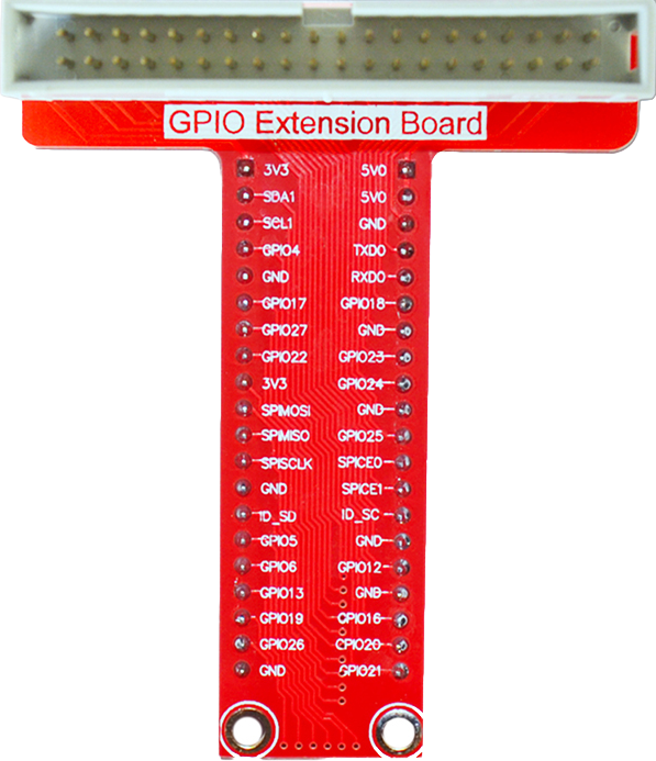
Pin Configuration and Descriptions
The GPIO Extension Board typically includes a header for connection to the microcontroller and additional GPIO pins for peripherals. Below is an example pinout for a 16-pin GPIO Extension Board:
| Pin | Label | Description |
|---|---|---|
| 1 | VCC | Power supply input (3.3V or 5V) |
| 2 | GND | Ground connection |
| 3 | SDA | I2C Data Line (if using I2C communication) |
| 4 | SCL | I2C Clock Line (if using I2C communication) |
| 5-20 | GPIO0 - GPIO15 | General Purpose Input/Output pins for peripherals |
Note: The exact pin configuration may vary depending on the specific GPIO Extension Board model. Always refer to the manufacturer's datasheet for precise details.
Usage Instructions
How to Use the GPIO Extension Board in a Circuit
- Connect Power and Ground: Attach the VCC and GND pins of the GPIO Extension Board to the corresponding pins on your microcontroller or SBC.
- Interface Selection: If the board uses I2C or SPI, connect the SDA/SCL or MOSI/MISO/CLK pins to the appropriate pins on your microcontroller.
- Connect Peripherals: Attach sensors, actuators, or other devices to the GPIO pins on the extension board.
- Configure Software: Use the appropriate library or code to initialize and control the GPIO pins.
Important Considerations and Best Practices
- Voltage Compatibility: Ensure the GPIO Extension Board operates at the same voltage level as your microcontroller (e.g., 3.3V or 5V).
- Current Limits: Do not exceed the maximum current rating for each GPIO pin to avoid damage.
- Pull-Up/Pull-Down Resistors: Use pull-up or pull-down resistors as needed for stable input signals.
- Avoid Short Circuits: Double-check connections to prevent accidental shorts that could damage the board or connected devices.
Example: Using the GPIO Extension Board with Arduino UNO
Below is an example code snippet for controlling an LED connected to a GPIO pin on the extension board using I2C communication:
#include <Wire.h> // Include the Wire library for I2C communication

#define I2C_ADDRESS 0x20 // Replace with the I2C address of your GPIO Extension Board

void setup() {
  Wire.begin(); // Initialize I2C communication
  pinMode(13, OUTPUT); // Set the onboard LED pin for debugging
  digitalWrite(13, LOW); // Turn off the onboard LED initially

  // Configure GPIO pins on the extension board
  Wire.beginTransmission(I2C_ADDRESS);
  Wire.write(0x00); // Command to set GPIO pins as outputs
  Wire.write(0xFF); // Set all pins to LOW initially
  Wire.endTransmission();
}

void loop() {
  // Turn on a GPIO pin (e.g., GPIO0)
  Wire.beginTransmission(I2C_ADDRESS);
  Wire.write(0x01); // Command to set GPIO0 HIGH
  Wire.endTransmission();
  delay(1000); // Wait for 1 second

  // Turn off the GPIO pin
  Wire.beginTransmission(I2C_ADDRESS);
  Wire.write(0x00); // Command to set GPIO0 LOW
  Wire.endTransmission();
  delay(1000); // Wait for 1 second
}
Note: Replace
I2C_ADDRESSand commands with the appropriate values for your specific GPIO Extension Board.
Troubleshooting and FAQs
Common Issues and Solutions
GPIO Pins Not Responding:
- Cause: Incorrect wiring or configuration.
- Solution: Verify all connections and ensure the board is powered correctly. Check the I2C/SPI address and communication settings.
Overheating:
- Cause: Exceeding the current limit of GPIO pins.
- Solution: Reduce the load on the pins or use external transistors/relays for high-current devices.
Peripheral Devices Not Working:
- Cause: Voltage mismatch or missing pull-up/pull-down resistors.
- Solution: Ensure voltage levels match and add resistors as needed.
I2C Communication Fails:
- Cause: Incorrect I2C address or wiring.
- Solution: Use an I2C scanner sketch to detect the correct address and verify SDA/SCL connections.
FAQs
Can I use the GPIO Extension Board with a Raspberry Pi? Yes, most GPIO Extension Boards are compatible with Raspberry Pi. Ensure the voltage levels match (3.3V for Raspberry Pi).
How many GPIO pins can I add with an extension board? This depends on the specific board. Common models provide 16, 32, or more GPIO pins.
Do I need additional drivers or libraries? For I2C or SPI-based boards, you may need to install specific libraries. Check the manufacturer's documentation for details.
Can I connect multiple GPIO Extension Boards? Yes, if the boards support unique I2C addresses or separate SPI chip select lines, you can daisy-chain multiple boards.
By following this documentation, you can effectively integrate and troubleshoot a GPIO Extension Board in your projects.