How to Use Mini Boost Converter 1A - 5/8/9/12V Fixed: Examples, Pinouts, and Specs
Introduction
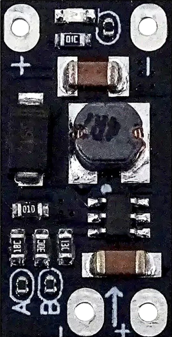
The Mini Boost Converter 1A - 5/8/9/12V Fixed is a compact DC-DC step-up converter designed to increase a lower input voltage to a fixed higher output voltage. It supports output voltage levels of 5V, 8V, 9V, or 12V, selectable via onboard configuration. With a maximum output current of 1A, this module is ideal for powering low-voltage devices such as microcontrollers, sensors, and small electronic projects from a single-cell battery or other low-voltage sources.
Explore Projects Built with Mini Boost Converter 1A - 5/8/9/12V Fixed


Explore Projects Built with Mini Boost Converter 1A - 5/8/9/12V Fixed
Common Applications
- Powering microcontrollers (e.g., Arduino, ESP32) from a single-cell Li-ion battery.
- Driving small DC motors or LEDs requiring a higher voltage.
- Portable electronics and battery-powered devices.
- DIY electronics projects requiring a compact voltage boost solution.
Technical Specifications
Key Technical Details
| Parameter | Value |
|---|---|
| Input Voltage Range | 2V to 24V |
| Output Voltage Options | 5V, 8V, 9V, 12V (fixed, selectable) |
| Maximum Output Current | 1A |
| Efficiency | Up to 92% (depending on input/output load) |
| Dimensions | 22mm x 17mm x 4mm |
| Operating Temperature | -40°C to +85°C |
Pin Configuration and Descriptions
| Pin Name | Description |
|---|---|
| VIN | Positive input voltage (2V to 24V). Connect to the power source. |
| GND | Ground connection. Connect to the negative terminal of the power source. |
| VOUT | Positive output voltage (5V, 8V, 9V, or 12V). Connect to the load device. |
Usage Instructions
How to Use the Mini Boost Converter in a Circuit
Input Voltage Connection:
- Connect the VIN pin to the positive terminal of your power source (e.g., a battery).
- Connect the GND pin to the negative terminal of the power source.
- Ensure the input voltage is within the range of 2V to 24V.
Output Voltage Selection:
- The module is pre-configured to output a fixed voltage (5V, 8V, 9V, or 12V).
- Check the product label or documentation to confirm the preset output voltage.
- If adjustable, refer to the manufacturer's instructions for changing the output voltage.
Output Voltage Connection:
- Connect the VOUT pin to the positive terminal of your load (e.g., microcontroller, motor).
- Connect the load's ground to the GND pin of the module.
Power On:
- Once all connections are secure, power on the input source.
- Verify the output voltage using a multimeter before connecting sensitive devices.
Important Considerations and Best Practices
- Input Voltage Range: Ensure the input voltage is within the specified range (2V to 24V). Exceeding this range may damage the module.
- Output Current Limit: Do not exceed the maximum output current of 1A to prevent overheating or damage.
- Heat Dissipation: For high loads, ensure proper ventilation or add a heatsink to prevent overheating.
- Polarity: Double-check the polarity of the input and output connections to avoid damage.
- Testing: Use a multimeter to verify the output voltage before connecting sensitive devices.
Example: Using the Mini Boost Converter with an Arduino UNO
To power an Arduino UNO from a 3.7V Li-ion battery using the Mini Boost Converter (set to 5V output):
- Connect the VIN pin of the converter to the positive terminal of the battery.
- Connect the GND pin of the converter to the negative terminal of the battery.
- Connect the VOUT pin of the converter to the 5V pin of the Arduino UNO.
- Connect the GND pin of the converter to the GND pin of the Arduino UNO.
Here is a simple Arduino sketch to blink an LED, powered by the Mini Boost Converter:
// Blink an LED connected to pin 13 of the Arduino UNO
// Ensure the Arduino is powered via the Mini Boost Converter (5V output)

void setup() {
  pinMode(13, OUTPUT); // Set pin 13 as an output
}

void loop() {
  digitalWrite(13, HIGH); // Turn the LED on
  delay(1000);            // Wait for 1 second
  digitalWrite(13, LOW);  // Turn the LED off
  delay(1000);            // Wait for 1 second
}
Troubleshooting and FAQs
Common Issues and Solutions
No Output Voltage:
- Cause: Incorrect input voltage or loose connections.
- Solution: Verify the input voltage is within the range of 2V to 24V. Check all connections.
Output Voltage Too Low or Unstable:
- Cause: Input voltage is too low or the load exceeds 1A.
- Solution: Ensure the input voltage is sufficient and the load current is within the 1A limit.
Module Overheating:
- Cause: Prolonged operation at high current or poor ventilation.
- Solution: Reduce the load current or improve heat dissipation with a heatsink.
Device Not Powering On:
- Cause: Incorrect polarity or damaged module.
- Solution: Double-check the polarity of all connections. Replace the module if damaged.
FAQs
Q: Can I adjust the output voltage?
A: The output voltage is fixed to one of the preset values (5V, 8V, 9V, or 12V). Refer to the manufacturer's instructions for reconfiguration if supported.Q: What happens if I exceed the 1A current limit?
A: Exceeding the current limit may cause the module to overheat, shut down, or become permanently damaged.Q: Can I use this module with a solar panel?
A: Yes, as long as the solar panel's output voltage is within the input range (2V to 24V) and provides sufficient current.Q: Is the module protected against reverse polarity?
A: No, the module does not have built-in reverse polarity protection. Always double-check your connections.
This concludes the documentation for the Mini Boost Converter 1A - 5/8/9/12V Fixed. For further assistance, refer to the manufacturer's support resources.