How to Use wireless power reciever coil: Examples, Pinouts, and Specs
Introduction
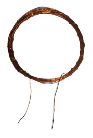
The Wireless Power Receiver Coil (Manufacturer Part ID: receiver coil 15 turns) by DIY is a key component in inductive charging systems. It is designed to receive energy wirelessly from a transmitter coil by converting the electromagnetic field into electrical energy. This energy can then be used to power electronic devices or charge batteries.
Explore Projects Built with wireless power reciever coil

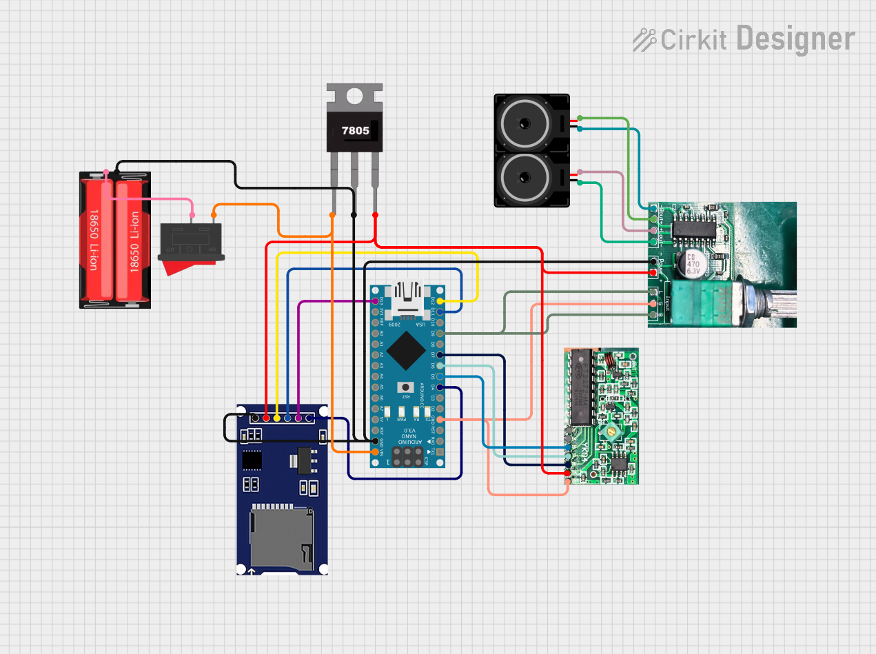
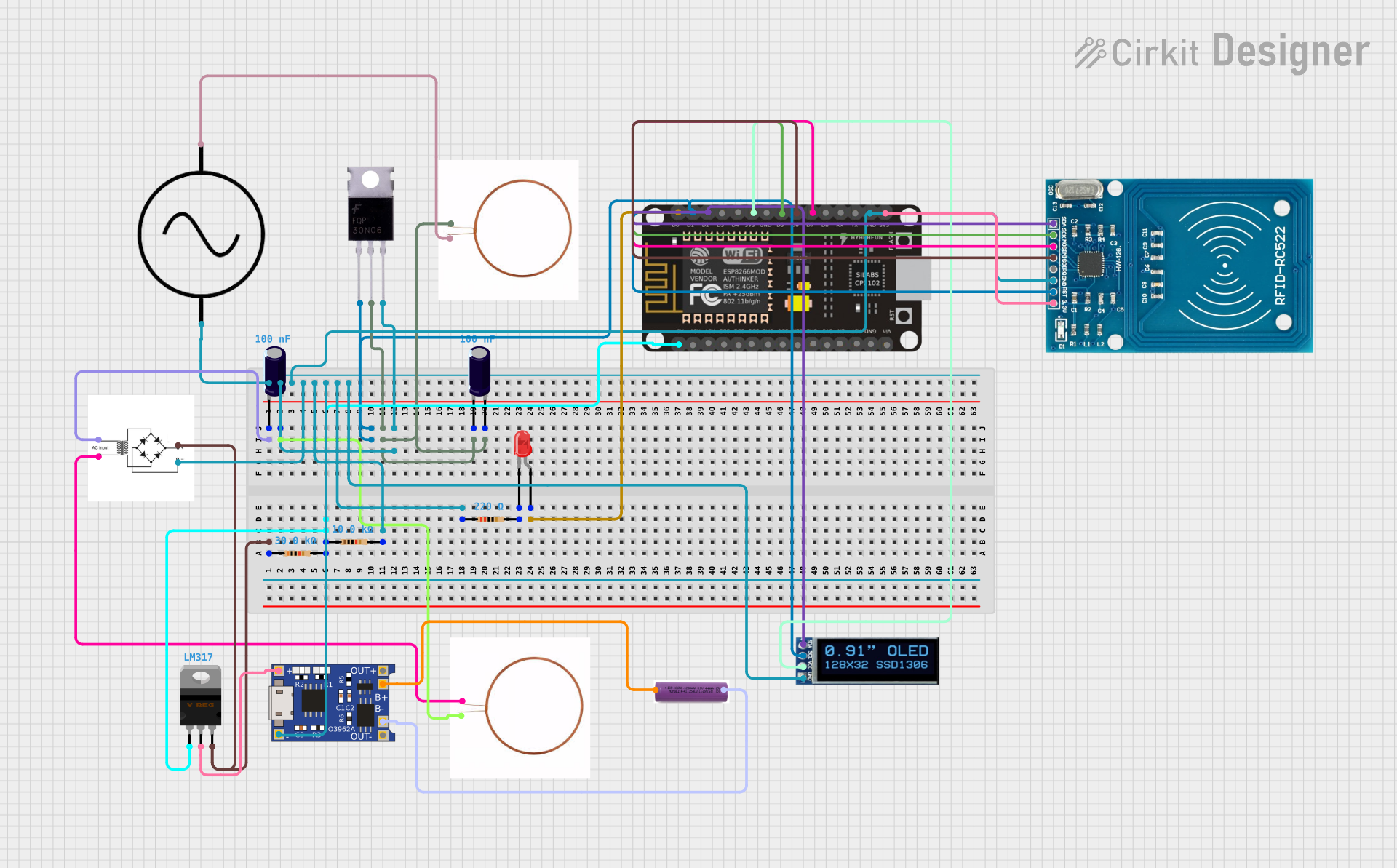

Explore Projects Built with wireless power reciever coil
Common Applications and Use Cases:
- Wireless charging pads for smartphones, smartwatches, and other portable devices.
- Wireless power transfer systems for IoT devices.
- Embedded systems requiring contactless power delivery.
- Prototyping and development of wireless energy transfer projects.
Technical Specifications
Below are the key technical details for the Wireless Power Receiver Coil:
| Parameter | Value |
|---|---|
| Manufacturer | DIY |
| Part ID | receiver coil 15 turns |
| Coil Turns | 15 |
| Inductance | 10 µH (typical) |
| Operating Frequency | 100 kHz – 200 kHz |
| Maximum Input Power | 5 W |
| Output Voltage | 5 V (typical, depending on rectifier circuit) |
| Efficiency | Up to 85% (depending on system design) |
| Dimensions | 40 mm diameter |
| Wire Material | Enameled copper wire |
Pin Configuration and Descriptions
The receiver coil itself does not have traditional "pins" but rather two wire leads for connection. These leads are typically connected to a rectifier circuit to convert the AC signal induced in the coil into DC power.
| Lead | Description |
|---|---|
| Lead 1 | Positive output from the coil (AC signal) |
| Lead 2 | Negative output from the coil (AC signal) |
Usage Instructions
How to Use the Component in a Circuit
Connect the Coil to a Rectifier Circuit:
The receiver coil generates an alternating current (AC) signal when placed in the electromagnetic field of a transmitter coil. To use this energy, connect the two leads of the coil to a rectifier circuit (e.g., a bridge rectifier) to convert the AC signal into a direct current (DC) output.Add a Voltage Regulator (Optional):
If a stable DC voltage is required, use a voltage regulator (e.g., LM7805 for 5V output) after the rectifier circuit.Positioning for Maximum Efficiency:
- Align the receiver coil with the transmitter coil for optimal coupling.
- Maintain a small air gap between the coils (typically 2–5 mm) for efficient energy transfer.
Load Connection:
Connect the output of the rectifier (or voltage regulator) to the load (e.g., a battery or electronic device).
Important Considerations and Best Practices
- Frequency Matching: Ensure the operating frequency of the transmitter coil matches the receiver coil's range (100 kHz – 200 kHz).
- Thermal Management: Avoid overheating by ensuring proper ventilation or heat dissipation in high-power applications.
- Alignment: Misalignment between the transmitter and receiver coils can significantly reduce efficiency.
- Testing: Use an oscilloscope to verify the AC signal generated by the receiver coil before rectification.
Example: Connecting to an Arduino UNO
To use the receiver coil with an Arduino UNO, you can power the Arduino via its 5V input pin after rectifying and regulating the coil's output. Below is an example circuit and code to monitor the voltage:
Circuit:
- Connect the receiver coil to a bridge rectifier.
- Add a capacitor (e.g., 100 µF) across the rectifier output for smoothing.
- Use a 5V voltage regulator to stabilize the output.
- Connect the regulated 5V output to the Arduino's 5V pin and GND.
Code:
// Arduino code to monitor the voltage from the wireless power receiver coil
const int voltagePin = A0; // Analog pin to read voltage
float voltage = 0.0;

void setup() {
  Serial.begin(9600); // Initialize serial communication
  pinMode(voltagePin, INPUT); // Set the voltage pin as input
}

void loop() {
  int sensorValue = analogRead(voltagePin); // Read the analog value
  voltage = sensorValue * (5.0 / 1023.0); // Convert to voltage (5V reference)

  // Print the voltage to the Serial Monitor
  Serial.print("Voltage: ");
  Serial.print(voltage);
  Serial.println(" V");

  delay(1000); // Wait for 1 second before the next reading
}
Troubleshooting and FAQs
Common Issues and Solutions
No Output Voltage:
Cause: Misalignment between the transmitter and receiver coils.
Solution: Adjust the position of the receiver coil to align it with the transmitter.
Cause: Faulty rectifier circuit.
Solution: Check the rectifier diodes for proper orientation and functionality.
Low Efficiency:
Cause: Large air gap between the coils.
Solution: Reduce the distance between the transmitter and receiver coils.
Cause: Frequency mismatch.
Solution: Ensure the transmitter operates within the receiver coil's frequency range (100 kHz – 200 kHz).
Overheating:
- Cause: Excessive power transfer or poor ventilation.
- Solution: Reduce the input power or improve heat dissipation.
FAQs
Q: Can this coil be used for high-power applications?
A: No, this coil is designed for low-power applications with a maximum input power of 5 W.Q: What is the typical output voltage of the coil?
A: The output voltage depends on the rectifier and load but is typically 5V after regulation.Q: Can I use this coil with a custom transmitter?
A: Yes, as long as the transmitter operates within the coil's frequency range and power limits.Q: How do I test the coil's functionality?
A: Use an oscilloscope to measure the AC signal generated by the coil when placed near an active transmitter.
This concludes the documentation for the Wireless Power Receiver Coil. For further assistance, refer to the manufacturer's support resources.