How to Use Wemos D1 Mini Relay Shield: Examples, Pinouts, and Specs
Introduction
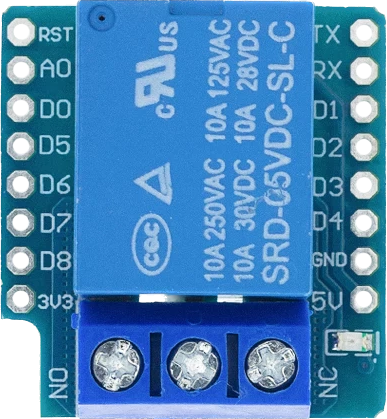
The Wemos D1 Mini Relay Shield is an expansion board designed to be used with the Wemos D1 Mini microcontroller. It provides the ability to control high-power devices such as home appliances and industrial equipment. This shield features a relay that can switch on and off by the D1 Mini, allowing for the control of devices that operate at higher voltages and currents than the D1 Mini can handle directly.
Explore Projects Built with Wemos D1 Mini Relay Shield
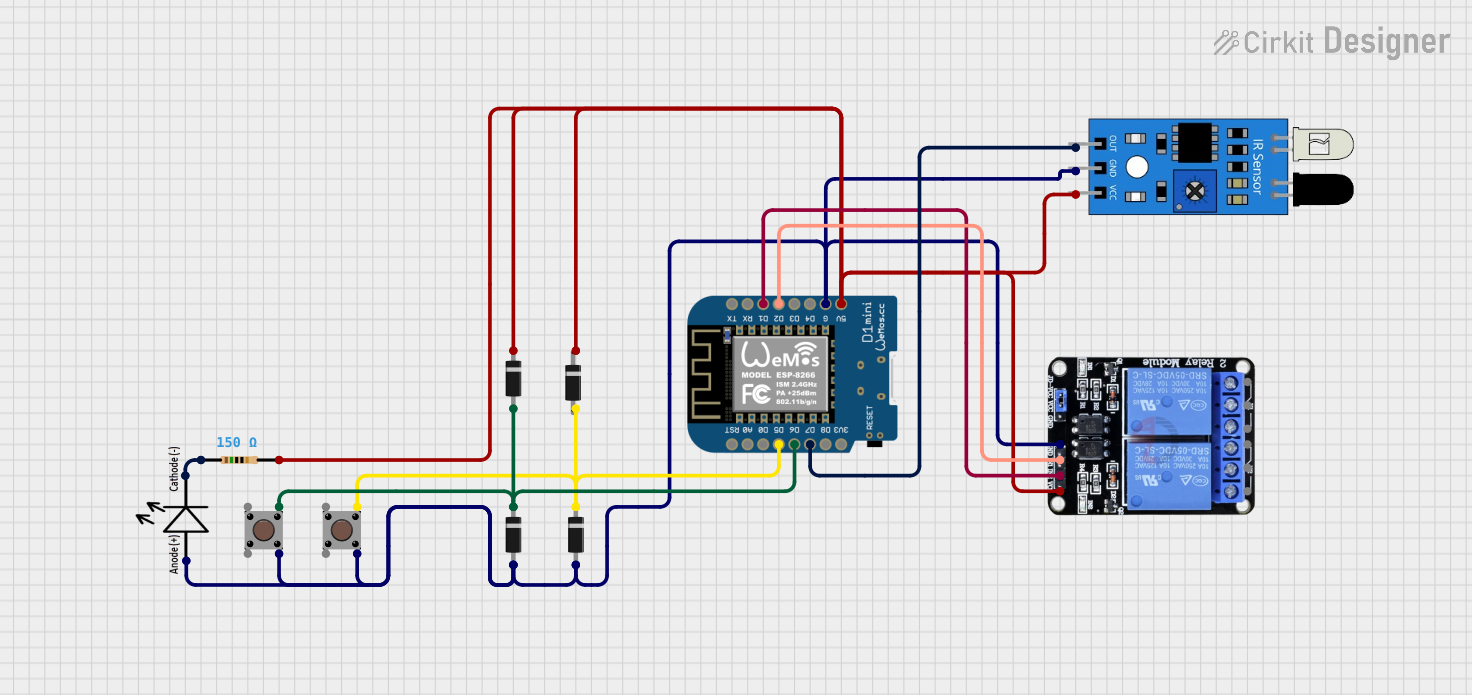

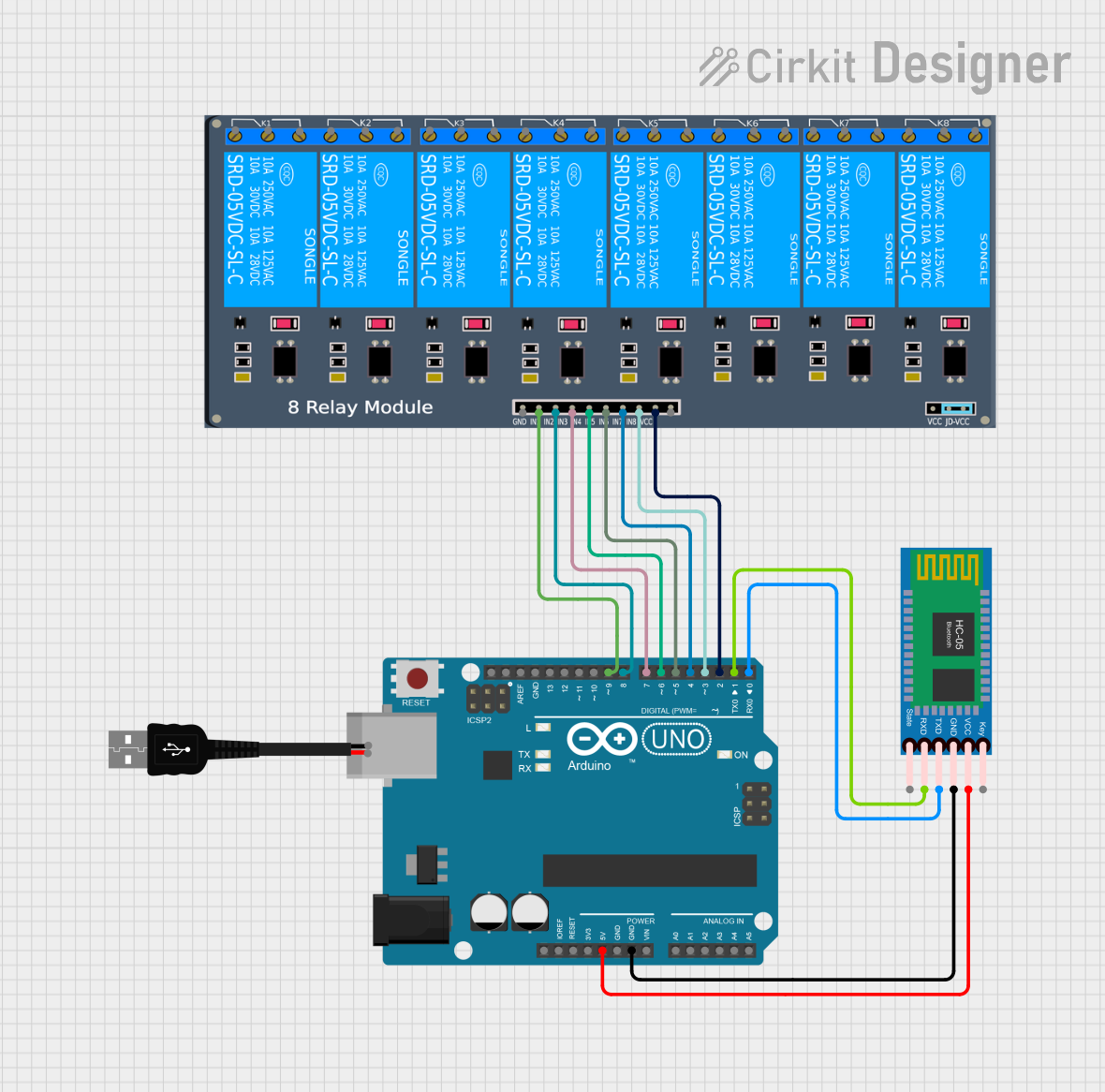
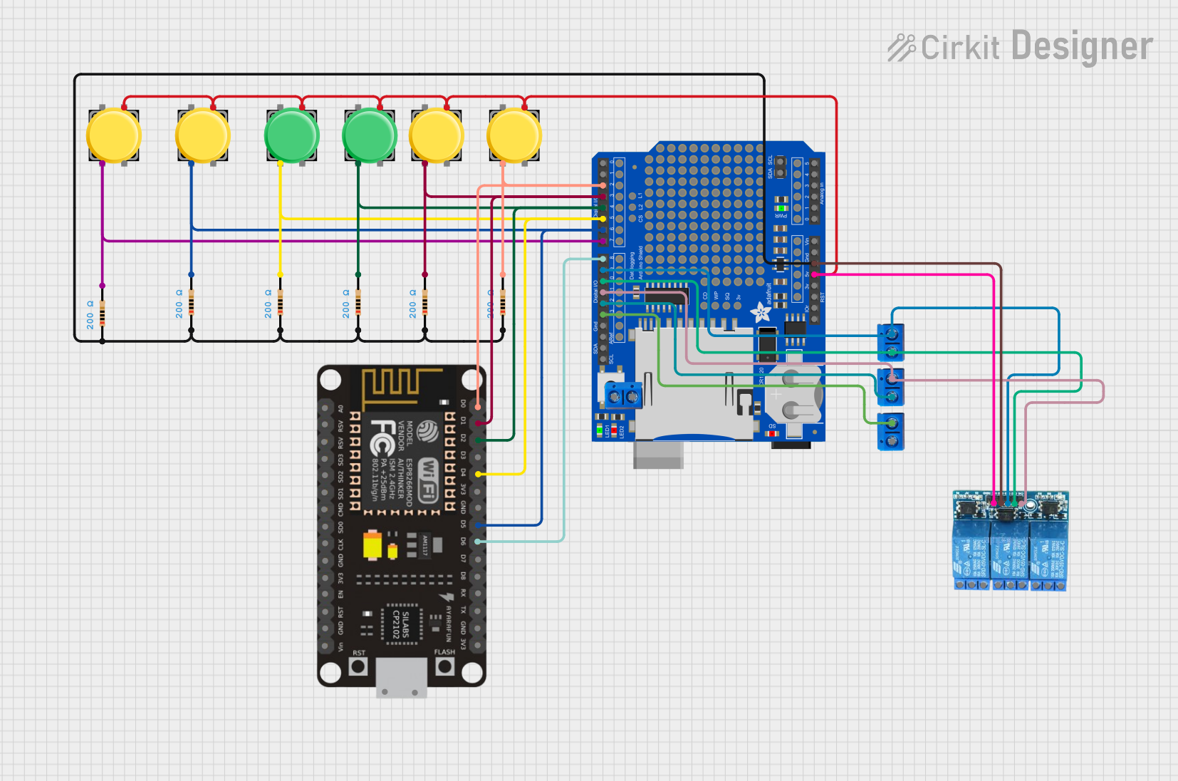
Explore Projects Built with Wemos D1 Mini Relay Shield
Common Applications and Use Cases
- Home automation (e.g., controlling lights, fans, and other household appliances)
- Industrial control systems
- Remote power switching
- Prototyping IoT (Internet of Things) devices
Technical Specifications
Key Technical Details
- Operating Voltage: 5V (supplied by the D1 Mini)
- Relay Type: SPDT (Single Pole Double Throw)
- Contact Rating: 10A 250VAC / 10A 30VDC
- Control Signal: Digital (High/Low)
- Dimensions: Matched to Wemos D1 Mini footprint
Pin Configuration and Descriptions
| Pin | Description |
|---|---|
| D1 | Relay control signal (active high) |
| 5V | Power supply to the relay coil (from D1 Mini 5V) |
| GND | Ground connection |
Usage Instructions
How to Use the Component in a Circuit
- Mount the Relay Shield on top of the Wemos D1 Mini by aligning the pins and gently pressing down.
- Connect the device you wish to control to the relay's Normally Open (NO) and Common (COM) terminals.
- Ensure that the Wemos D1 Mini is programmed to control the relay via the D1 pin.
Important Considerations and Best Practices
- Always ensure the power ratings of the relay are not exceeded by the connected device.
- When controlling AC devices, it is crucial to take proper safety precautions to avoid electric shock.
- Use flyback diodes when necessary to protect against voltage spikes when switching inductive loads.
- Ensure that the Wemos D1 Mini is disconnected from power when assembling or modifying the circuit.
Example Code for Arduino UNO
// Example code to control the Wemos D1 Mini Relay Shield
// The relay is controlled by setting pin D1 to HIGH or LOW.

#define RELAY_PIN D1 // Define the relay control pin

void setup() {
  pinMode(RELAY_PIN, OUTPUT); // Set the relay pin as an output
}

void loop() {
  digitalWrite(RELAY_PIN, HIGH); // Turn on the relay
  delay(1000);                   // Wait for 1 second
  digitalWrite(RELAY_PIN, LOW);  // Turn off the relay
  delay(1000);                   // Wait for 1 second
}
Troubleshooting and FAQs
Common Issues Users Might Face
- Relay does not switch: Ensure that the D1 Mini is correctly powered and the D1 pin is being set to HIGH.
- Intermittent operation: Check for loose connections and ensure that the relay shield is properly seated on the D1 Mini.
- Device not responding: Verify that the connected device's power requirements do not exceed the relay's rating.
Solutions and Tips for Troubleshooting
- Double-check wiring and solder joints for any cold solder or loose connections.
- Use a multimeter to verify the presence of control voltage at the relay's input.
- Ensure that the code uploaded to the D1 Mini correctly addresses the relay control pin.
FAQs
Q: Can I control multiple Relay Shields with one D1 Mini? A: Yes, but you will need to use separate control pins for each relay and stack the shields with care to avoid pin conflicts.
Q: Is it safe to control AC devices with the Relay Shield? A: While the relay is rated for AC control, safety precautions must be taken, including proper insulation and avoiding contact with live wiring.
Q: Can I use the Relay Shield with other microcontrollers? A: Yes, as long as the microcontroller can provide the necessary control signal and power to the relay.
Remember to always follow safety guidelines when working with high voltage and current. If you are not experienced with electrical systems, seek assistance from a qualified individual.