How to Use Piezo Buzzer: Examples, Pinouts, and Specs

Introduction
A piezo buzzer is a compact and versatile electronic sound-producing device that operates on the principle of the piezoelectric effect. When an electric signal is applied to a piezoelectric material, it deforms and generates an audible sound. Piezo buzzers are widely used in various applications such as alarm clocks, kitchen timers, computer devices, toys, and as alert signals in medical and industrial equipment due to their reliability and simplicity.
Explore Projects Built with Piezo Buzzer
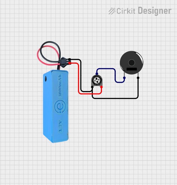
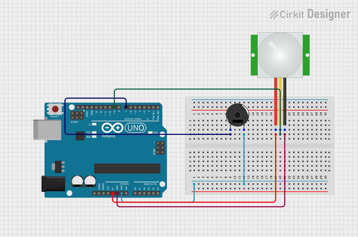
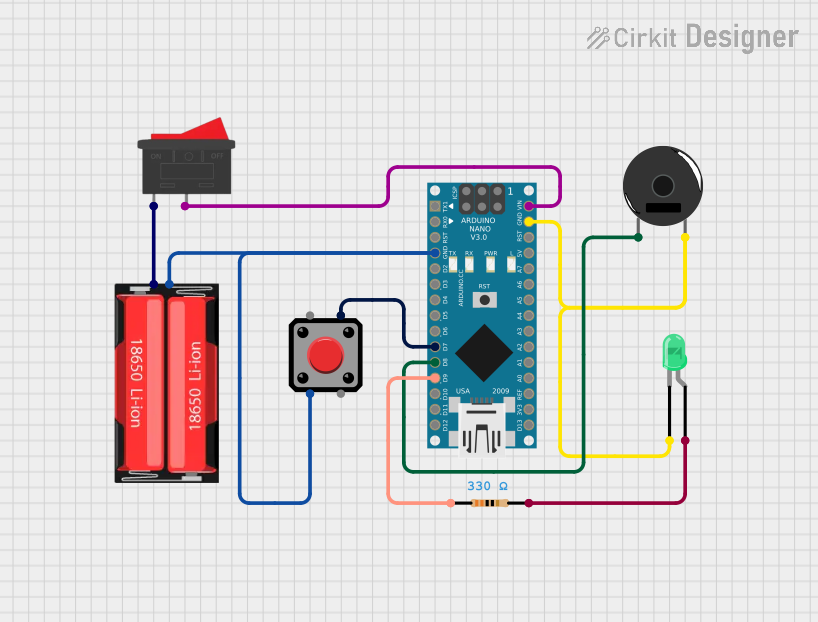
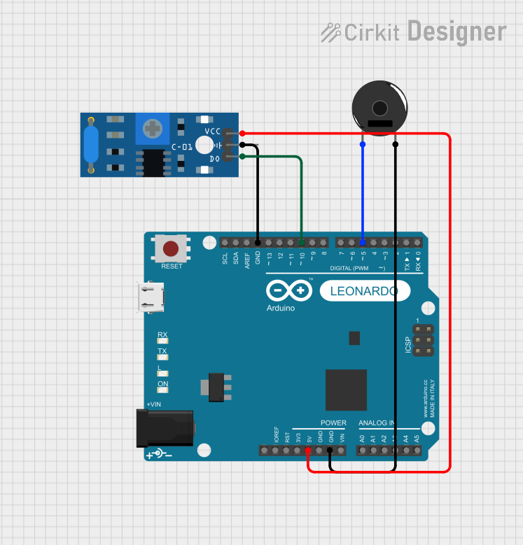
Explore Projects Built with Piezo Buzzer
Technical Specifications
Key Technical Details
- Rated Voltage: Typically 3V to 12V
- Operating Current: 5mA to 30mA (varies by model)
- Sound Output: 70dB to 90dB at 10cm (varies by model)
- Resonant Frequency: 2kHz to 4kHz (commonly used frequency)
- Operating Temperature: -20°C to +70°C
Pin Configuration and Descriptions
| Pin Number | Description |
|---|---|
| 1 | Positive (V+) |
| 2 | Negative (Ground, GND) |
Usage Instructions
How to Use the Component in a Circuit
- Identify the Pins: Locate the positive and negative pins of the piezo buzzer. The positive pin is typically longer than the negative pin.
- Connect to Power Source: Connect the positive pin to the output pin of a microcontroller or a digital circuit, and the negative pin to the ground.
- Drive with a Signal: To produce sound, drive the piezo buzzer with a square wave at its resonant frequency. The frequency of the square wave will determine the pitch of the sound.
Important Considerations and Best Practices
- Voltage Rating: Do not exceed the rated voltage of the piezo buzzer as it may damage the component.
- Driving Circuit: Use a driving circuit if the buzzer requires more current than the microcontroller pin can supply.
- Frequency: For optimal sound output, operate the buzzer at or near its resonant frequency.
- Pulse Width Modulation (PWM): Use PWM to control the volume and tone of the buzzer.
Example Code for Arduino UNO
// Define the buzzer pin
int buzzerPin = 9;

void setup() {
  // Set the buzzer pin as an output
  pinMode(buzzerPin, OUTPUT);
}

void loop() {
  // Produce a 2kHz tone for 1 second
  tone(buzzerPin, 2000); // Send a 2kHz sound signal...
  delay(1000);           // ...for 1 second
  noTone(buzzerPin);     // Stop the tone
  delay(1000);           // Wait for 1 second
}
Troubleshooting and FAQs
Common Issues
- No Sound: Ensure the buzzer is correctly connected with the right polarity and the driving signal is within the buzzer's operating frequency range.
- Low Sound Output: Check if the voltage is within the rated range and the buzzer is being driven at its resonant frequency.
- Distorted Sound: Verify that the buzzer is not being overdriven with a voltage higher than its rating.
Solutions and Tips for Troubleshooting
- Check Connections: Revisit the circuit connections and ensure proper contact.
- Test with a Multimeter: Use a multimeter to check for continuity and proper voltage levels at the buzzer pins.
- Replace the Buzzer: If the buzzer is still not functioning, it may be defective and need replacement.
FAQs
Q: Can I use a piezo buzzer with a battery? A: Yes, as long as the battery voltage matches the buzzer's rated voltage.
Q: How can I change the sound frequency of the buzzer?
A: Adjust the frequency of the input signal. In the Arduino example, change the value in the tone() function.
Q: Is it possible to play melodies with a piezo buzzer? A: Yes, by varying the frequency and duration of the input signal, you can create simple melodies.
Q: Can I control the volume of the piezo buzzer? A: The volume can be somewhat controlled by varying the voltage or using PWM, but piezo buzzers have limited volume control compared to other audio devices.