How to Use Riverdi Display: Examples, Pinouts, and Specs
Introduction
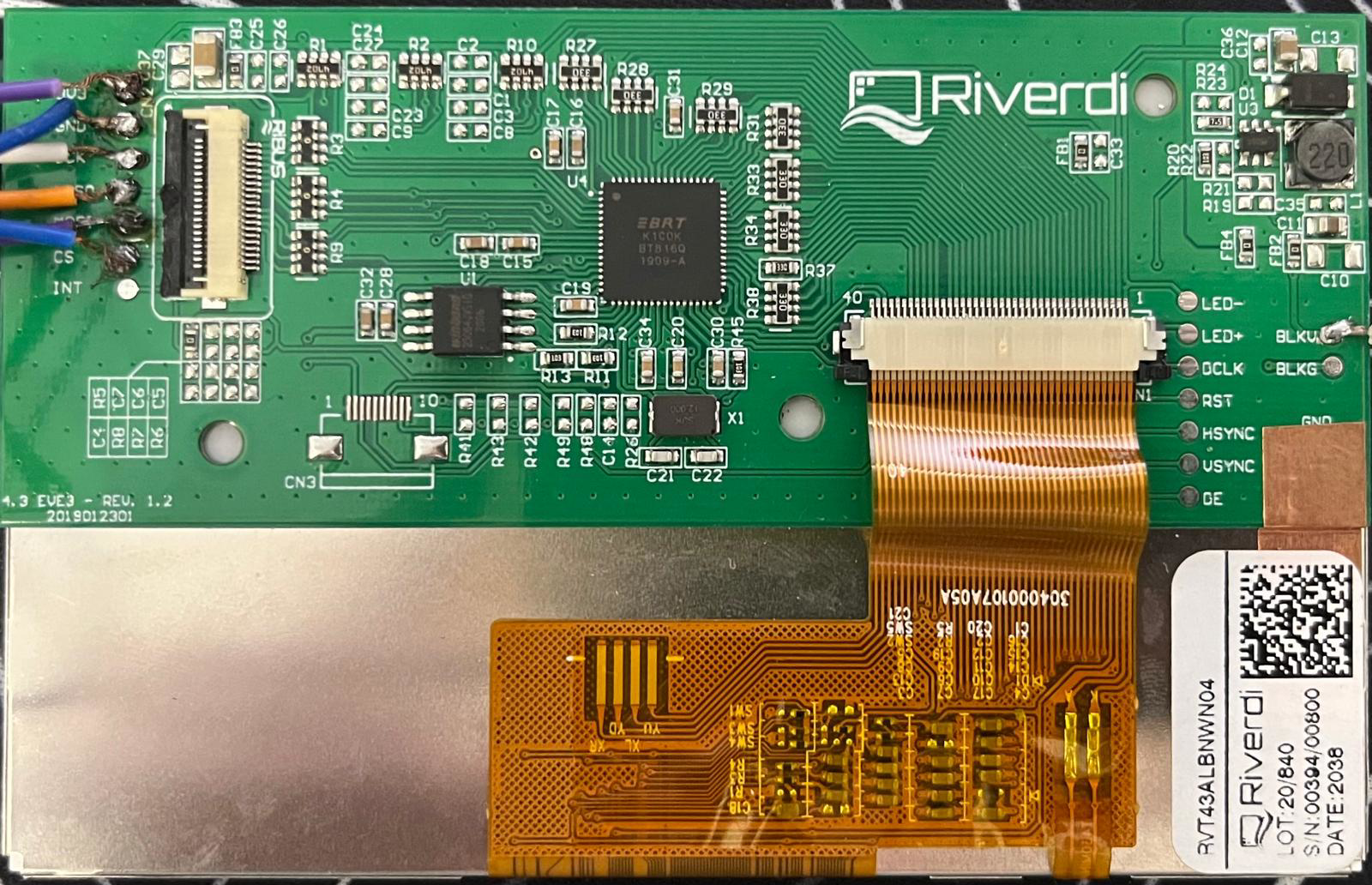
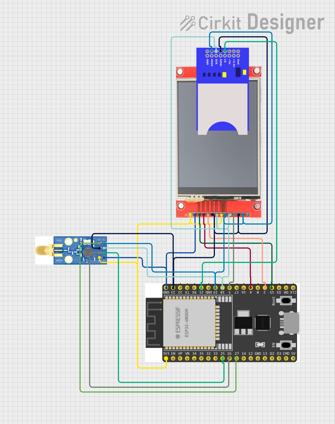
The Riverdi Display is a high-quality graphical display module designed for embedded systems. It is available in various sizes and resolutions, offering flexibility for a wide range of applications. Many models include touch capabilities, making them ideal for interactive interfaces. With support for communication protocols like SPI and I2C, the Riverdi Display is easy to integrate into microcontroller-based projects.
Explore Projects Built with Riverdi Display
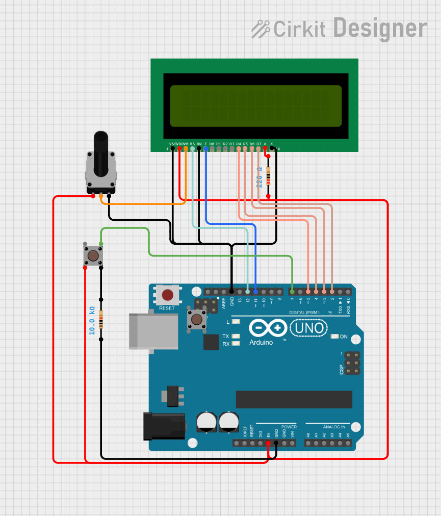
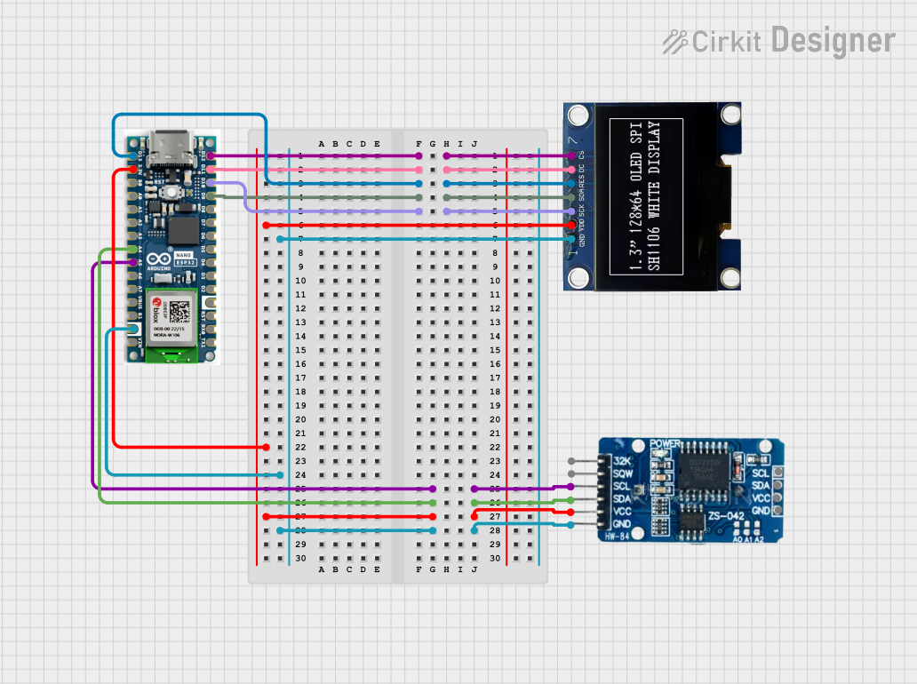
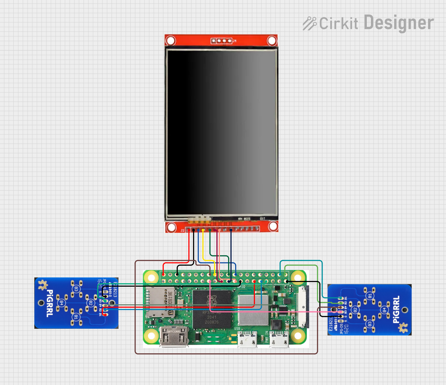
Explore Projects Built with Riverdi Display
Common Applications and Use Cases
- Industrial control panels
- Consumer electronics with graphical user interfaces
- IoT devices with visual feedback
- Medical devices requiring touch-enabled displays
- Prototyping and development of embedded systems
Technical Specifications
Below are the general technical specifications for the Riverdi Display. Note that specific models may vary slightly in their parameters.
Key Technical Details
- Display Type: TFT LCD
- Available Sizes: 2.8", 3.5", 4.3", 5.0", 7.0"
- Resolution: Ranges from 240x320 to 800x480 pixels
- Touch Options: Resistive or Capacitive Touch
- Interface: SPI, I2C, or Parallel RGB
- Operating Voltage: 3.3V or 5V (model-dependent)
- Backlight: LED with adjustable brightness
- Operating Temperature: -20°C to +70°C
- Controller IC: FT81x or BT81x series (for models with integrated controllers)
Pin Configuration and Descriptions
The pinout may vary depending on the specific model and interface. Below is an example pin configuration for a Riverdi Display with an SPI interface:
| Pin | Name | Description |
|---|---|---|
| 1 | VCC | Power supply input (3.3V or 5V, depending on the model). |
| 2 | GND | Ground connection. |
| 3 | CS | Chip Select pin for SPI communication. |
| 4 | SCK | Serial Clock pin for SPI communication. |
| 5 | MOSI | Master Out Slave In pin for SPI communication. |
| 6 | MISO | Master In Slave Out pin for SPI communication (if supported). |
| 7 | INT | Interrupt pin for signaling events (e.g., touch input). |
| 8 | RST | Reset pin to initialize the display. |
| 9 | BL_CTRL | Backlight control pin (PWM or digital signal for brightness adjustment). |
| 10 | TOUCH_INT | Interrupt pin for touch controller (if touch-enabled). |
For I2C-based models, the pinout typically includes SDA (data line) and SCL (clock line) instead of SPI-specific pins.
Usage Instructions
How to Use the Riverdi Display in a Circuit
- Power Supply: Connect the VCC pin to a 3.3V or 5V power source, depending on the model. Ensure the GND pin is connected to the ground of your circuit.
- Communication Interface:
- For SPI models, connect the CS, SCK, MOSI, and MISO pins to the corresponding pins on your microcontroller.
- For I2C models, connect the SDA and SCL pins to the appropriate I2C pins on your microcontroller.
- Backlight Control: Use the BL_CTRL pin to adjust the backlight brightness. This can be done using a PWM signal or a digital HIGH/LOW signal.
- Touch Functionality: If the display includes touch capabilities, connect the TOUCH_INT pin to an interrupt-capable pin on your microcontroller.
- Initialization: Use the RST pin to reset the display during startup or when reinitializing.
Important Considerations and Best Practices
- Voltage Compatibility: Verify the operating voltage of your specific Riverdi Display model to avoid damage.
- Signal Integrity: Use short and properly routed wires for SPI or I2C connections to minimize noise.
- Library Support: Many Riverdi Displays are compatible with libraries like the FTDI EVE library for Arduino, simplifying development.
- Touch Calibration: For touch-enabled models, ensure proper calibration for accurate input detection.
Example Code for Arduino UNO (SPI Interface)
Below is an example of initializing and displaying a simple graphic on a Riverdi Display using the FTDI EVE library:
#include <EVE.h> // Include the FTDI EVE library

#define CS_PIN 10  // Chip Select pin
#define PD_PIN 9   // Power Down pin
#define INT_PIN 8  // Interrupt pin

EVE eve(CS_PIN, PD_PIN, INT_PIN); // Create an EVE object

void setup() {
  pinMode(CS_PIN, OUTPUT);
  pinMode(PD_PIN, OUTPUT);
  pinMode(INT_PIN, INPUT);

  // Initialize the display
  eve.begin();
  eve.lcd_init();

  // Clear the screen and display a message
  eve.ClearColorRGB(0, 0, 0); // Set background color to black
  eve.Clear();                // Clear the screen
  eve.ColorRGB(255, 255, 255); // Set text color to white
  eve.cmd_text(240, 136, 31, EVE_OPT_CENTER, "Hello, Riverdi!"); // Display text
  eve.swap();                 // Update the display
}

void loop() {
  // Main loop can be used for further updates
}
Troubleshooting and FAQs
Common Issues and Solutions
Display Not Turning On
- Cause: Incorrect power supply or loose connections.
- Solution: Verify the VCC and GND connections and ensure the correct voltage is supplied.
No Output on the Screen
- Cause: Improper initialization or incorrect communication settings.
- Solution: Check the SPI or I2C connections and ensure the correct pins are defined in your code.
Touch Not Responding
- Cause: Touch controller not properly connected or calibrated.
- Solution: Verify the TOUCH_INT pin connection and perform touch calibration if required.
Flickering or Dim Backlight
- Cause: Insufficient power supply or incorrect backlight control signal.
- Solution: Ensure the power supply can handle the display's current requirements and verify the BL_CTRL signal.
FAQs
Can I use the Riverdi Display with a 5V microcontroller?
- Yes, but ensure the specific model supports 5V logic levels or use a level shifter for compatibility.
Which library should I use for Arduino?
- The FTDI EVE library is recommended for models with FT81x or BT81x controllers.
How do I adjust the brightness?
- Use a PWM signal on the BL_CTRL pin to control the backlight brightness.
Is the display compatible with Raspberry Pi?
- Yes, the Riverdi Display can be used with Raspberry Pi via SPI or I2C, but additional configuration may be required.
This documentation provides a comprehensive guide to using the Riverdi Display in your projects. For further assistance, refer to the official datasheet or support resources.