
How to Use OV5640 Breakout Board: Examples, Pinouts, and Specs
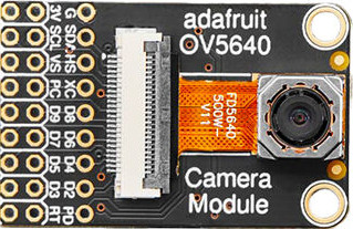
 Design with OV5640 Breakout Board in Cirkit Designer
Introduction
The OV5640 Breakout Board by Adafruit is a compact circuit board featuring the OV5640 image sensor. This sensor is capable of capturing high-resolution images and streaming video, making it ideal for a wide range of applications. The breakout board simplifies integration into projects by providing easy access to the sensor's functionality through a user-friendly pinout.
Explore Projects Built with OV5640 Breakout Board
 Open Project in Cirkit Designer
 Open Project in Cirkit Designer
 Open Project in Cirkit Designer
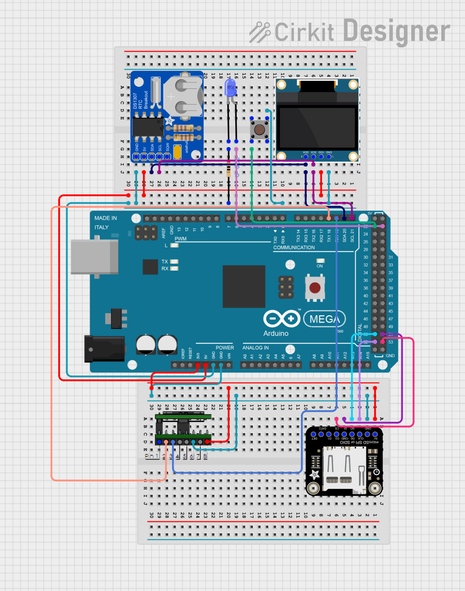 Open Project in Cirkit Designer
Explore Projects Built with OV5640 Breakout Board
Open Project in Cirkit DesignerOpen Project in Cirkit DesignerOpen Project in Cirkit DesignerOpen Project in Cirkit DesignerCommon Applications
- Embedded Vision Systems: Ideal for robotics, drones, and IoT devices requiring visual input.
- Surveillance and Security: Used in security cameras for high-quality image capture.
- Machine Learning Projects: Suitable for image recognition and object detection tasks.
- DIY Electronics: Perfect for hobbyists building custom cameras or video streaming devices.
Technical Specifications
The OV5640 Breakout Board is designed to provide high performance in a compact form factor. Below are the key technical details:
Key Specifications
| Parameter | Value |
|---|---|
| Image Sensor | OV5640 CMOS sensor |
| Resolution | Up to 5 megapixels (2592 x 1944) |
| Video Output | 1080p at 30 fps, 720p at 60 fps |
| Interface | DVP (Digital Video Port) and I2C |
| Operating Voltage | 3.3V (logic level) |
| Power Consumption | Low power, suitable for battery operation |
| Lens Type | Fixed focus lens |
| Dimensions | Compact breakout board (approx. 25x25 mm) |
Pin Configuration
The breakout board provides a set of pins for easy interfacing. Below is the pinout description:
| Pin Name | Type | Description |
|---|---|---|
| VCC | Power Input | 3.3V power supply input |
| GND | Ground | Ground connection |
| SCL | I2C Clock | Serial clock for I2C communication |
| SDA | I2C Data | Serial data for I2C communication |
| D0-D7 | Data Output | 8-bit parallel data output for video/image data |
| PCLK | Clock Output | Pixel clock for synchronizing data transfer |
| HREF | Signal Output | Horizontal reference signal |
| VSYNC | Signal Output | Vertical synchronization signal |
| RESET | Input | Active-low reset pin |
| PWDN | Input | Power-down mode control (active high) |
Usage Instructions
The OV5640 Breakout Board is straightforward to use in a variety of projects. Below are the steps and best practices for integrating it into your circuit.
Connecting the OV5640 to an Arduino UNO
- Power Supply: Connect the
VCCpin to the 3.3V output of the Arduino and theGNDpin to ground. - I2C Communication: Connect the
SCLpin to Arduino's A5 (SCL) and theSDApin to A4 (SDA). - Data Pins: Use the
D0-D7pins for parallel data output if required by your application. - Control Pins: Connect the
RESETpin to a digital pin on the Arduino for software resets. ThePWDNpin can be left unconnected if not used.
Sample Arduino Code
Below is an example of initializing the OV5640 using I2C communication with an Arduino UNO:
#include <Wire.h>

// OV5640 I2C address
#define OV5640_I2C_ADDR 0x78

void setup() {
  Wire.begin(); // Initialize I2C communication
  Serial.begin(9600); // Start serial communication for debugging

  // Reset the OV5640
  pinMode(7, OUTPUT); // Set pin 7 as output for RESET
  digitalWrite(7, LOW); // Hold RESET low
  delay(10); // Wait for 10ms
  digitalWrite(7, HIGH); // Release RESET
  delay(10); // Wait for the sensor to initialize

  // Initialize the OV5640
  if (initializeOV5640()) {
    Serial.println("OV5640 initialized successfully!");
  } else {
    Serial.println("Failed to initialize OV5640.");
  }
}

bool initializeOV5640() {
  Wire.beginTransmission(OV5640_I2C_ADDR);
  Wire.write(0x3008); // System control register
  Wire.write(0x80);   // Software reset
  if (Wire.endTransmission() != 0) {
    return false; // Return false if communication fails
  }
  delay(100); // Wait for the reset to complete
  return true;
}

void loop() {
  // Main loop can be used for capturing images or streaming video
}
Best Practices
- Power Supply: Ensure a stable 3.3V power source to avoid damaging the sensor.
- Signal Integrity: Use short wires for high-speed signals like
PCLKandD0-D7to minimize noise. - Lens Cleaning: Keep the lens clean for optimal image quality.
- Heat Management: Avoid placing the breakout board in high-temperature environments.
Troubleshooting and FAQs
Common Issues
No Image Output:
- Ensure the
VCCandGNDconnections are secure. - Verify that the
RESETpin is properly controlled during initialization. - Check the I2C communication lines (
SCLandSDA) for proper connections.
- Ensure the
Blurry Images:
- Ensure the lens is clean and free of dust or smudges.
- Verify that the object is within the fixed focus range of the lens.
I2C Communication Fails:
- Confirm the I2C address (
0x78) matches the sensor's default address. - Use pull-up resistors (4.7kΩ) on the
SCLandSDAlines if not already present.
- Confirm the I2C address (
Overheating:
- Check for proper ventilation around the breakout board.
- Ensure the power supply voltage does not exceed 3.3V.
FAQs
Q: Can the OV5640 Breakout Board capture video in low light?
A: Yes, the OV5640 sensor includes features like automatic exposure control and gain adjustment, which improve performance in low-light conditions.
Q: Is the OV5640 compatible with Raspberry Pi?
A: Yes, the OV5640 can be interfaced with Raspberry Pi using the I2C and DVP interfaces, but additional software configuration may be required.
Q: Can I use the OV5640 for real-time video streaming?
A: Yes, the OV5640 supports real-time video streaming at resolutions up to 1080p at 30 fps.
Q: What is the maximum cable length for I2C communication?
A: For reliable communication, keep the I2C cable length under 50 cm. Use shielded cables for longer distances.
By following this documentation, you can effectively integrate the OV5640 Breakout Board into your projects and troubleshoot common issues with ease.