How to Use Anti Reverse Connection Power Protection Board: Examples, Pinouts, and Specs

Introduction
The Anti Reverse Connection Power Protection Board, manufactured by DIY (Part ID: board), is a compact and reliable circuit board designed to safeguard electronic systems from damage caused by reverse polarity connections. This board ensures that electrical components are protected from incorrect voltage application, which can occur due to accidental miswiring or reversed power supply connections.
Explore Projects Built with Anti Reverse Connection Power Protection Board

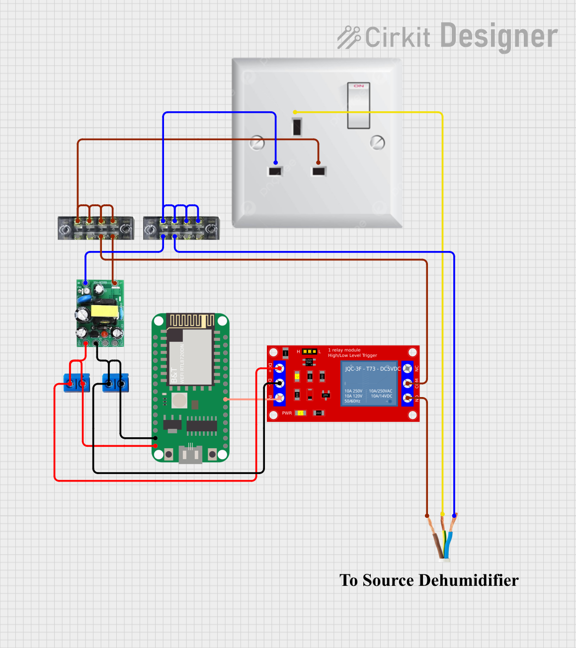

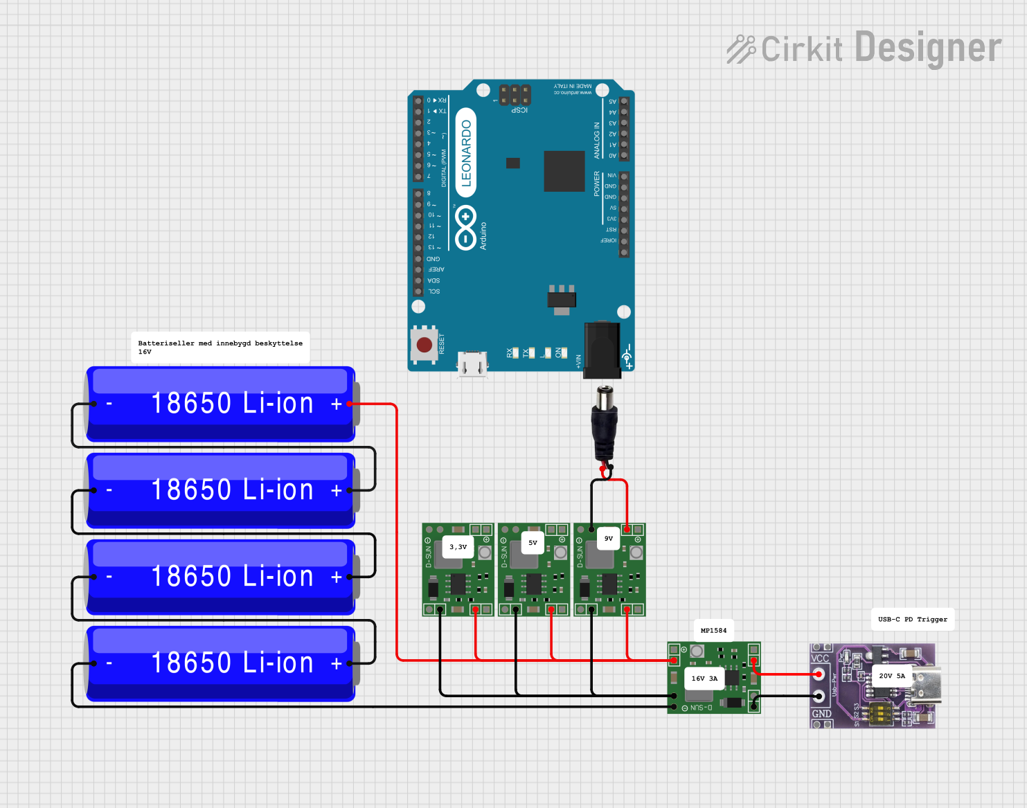
Explore Projects Built with Anti Reverse Connection Power Protection Board
Common Applications and Use Cases
- Protection of sensitive electronic devices in DIY projects.
- Integration into power supply systems for reverse polarity protection.
- Use in automotive electronics to prevent damage from incorrect battery connections.
- Safeguarding Arduino, Raspberry Pi, and other microcontroller-based systems.
Technical Specifications
The following table outlines the key technical details of the Anti Reverse Connection Power Protection Board:
| Parameter | Value |
|---|---|
| Input Voltage Range | 3V to 30V |
| Maximum Current | 10A |
| Voltage Drop | ~0.3V (depends on load current) |
| Board Dimensions | 25mm x 15mm x 5mm |
| Operating Temperature | -40°C to +85°C |
| Connector Type | Screw terminals for input/output |
Pin Configuration and Descriptions
The board features two sets of screw terminals for easy connection:
| Pin Name | Description |
|---|---|
VIN+ |
Positive input voltage terminal |
VIN- |
Negative input voltage terminal (ground) |
VOUT+ |
Positive output voltage terminal |
VOUT- |
Negative output voltage terminal (ground) |
Usage Instructions
How to Use the Component in a Circuit
Connect the Input Power Supply:
- Attach the positive terminal of your power source to the
VIN+terminal. - Attach the negative terminal of your power source to the
VIN-terminal.
- Attach the positive terminal of your power source to the
Connect the Load:
- Connect the positive terminal of your load (e.g., a microcontroller or motor) to the
VOUT+terminal. - Connect the negative terminal of your load to the
VOUT-terminal.
- Connect the positive terminal of your load (e.g., a microcontroller or motor) to the
Power On:
- Turn on the power supply. The board will automatically block any reverse polarity connection, ensuring that only the correct voltage is delivered to the load.
Important Considerations and Best Practices
- Voltage Drop: The board introduces a small voltage drop (~0.3V) due to the internal protection circuitry. Ensure that your power supply voltage is sufficient to account for this drop.
- Current Rating: Do not exceed the maximum current rating of 10A to avoid overheating or damage to the board.
- Secure Connections: Tighten the screw terminals securely to ensure reliable electrical connections.
- Polarity Check: While the board protects against reverse polarity, it is still good practice to double-check your connections before powering on.
Example: Using with an Arduino UNO
The Anti Reverse Connection Power Protection Board can be used to protect an Arduino UNO from reverse polarity. Below is an example circuit and Arduino code:
Circuit Setup
- Connect a 9V battery to the
VIN+andVIN-terminals of the board. - Connect the
VOUT+andVOUT-terminals to the Arduino'sVINandGNDpins, respectively.
Arduino Code
// Example code to blink an LED connected to pin 13 of the Arduino UNO
// This demonstrates the Arduino functioning correctly with reverse polarity protection.

void setup() {
  pinMode(13, OUTPUT); // Set pin 13 as an output for the LED
}

void loop() {
  digitalWrite(13, HIGH); // Turn the LED on
  delay(1000);            // Wait for 1 second
  digitalWrite(13, LOW);  // Turn the LED off
  delay(1000);            // Wait for 1 second
}
Troubleshooting and FAQs
Common Issues Users Might Face
No Output Voltage:
- Cause: Reverse polarity connection at the input terminals.
- Solution: Verify the polarity of the input power supply and ensure it is connected correctly.
Excessive Voltage Drop:
- Cause: High current draw exceeding the board's capacity.
- Solution: Ensure the load does not exceed the 10A maximum current rating.
Overheating:
- Cause: Prolonged operation at or near the maximum current rating.
- Solution: Reduce the load current or improve ventilation around the board.
Loose Connections:
- Cause: Poorly tightened screw terminals.
- Solution: Check and tighten all connections securely.
FAQs
Q: Can this board protect against overvoltage?
A: No, the board is designed specifically for reverse polarity protection. Use a separate overvoltage protection circuit if needed.
Q: Can I use this board with AC power?
A: No, this board is designed for DC power systems only. Using it with AC power may damage the board.
Q: What happens if I exceed the maximum current rating?
A: Exceeding the 10A limit may cause the board to overheat or fail. Always ensure your load stays within the specified current range.
Q: Is the board suitable for outdoor use?
A: The board is not weatherproof. If using it outdoors, enclose it in a waterproof housing to protect it from moisture and dust.