
How to Use V_REG_LD1117VXX: Examples, Pinouts, and Specs
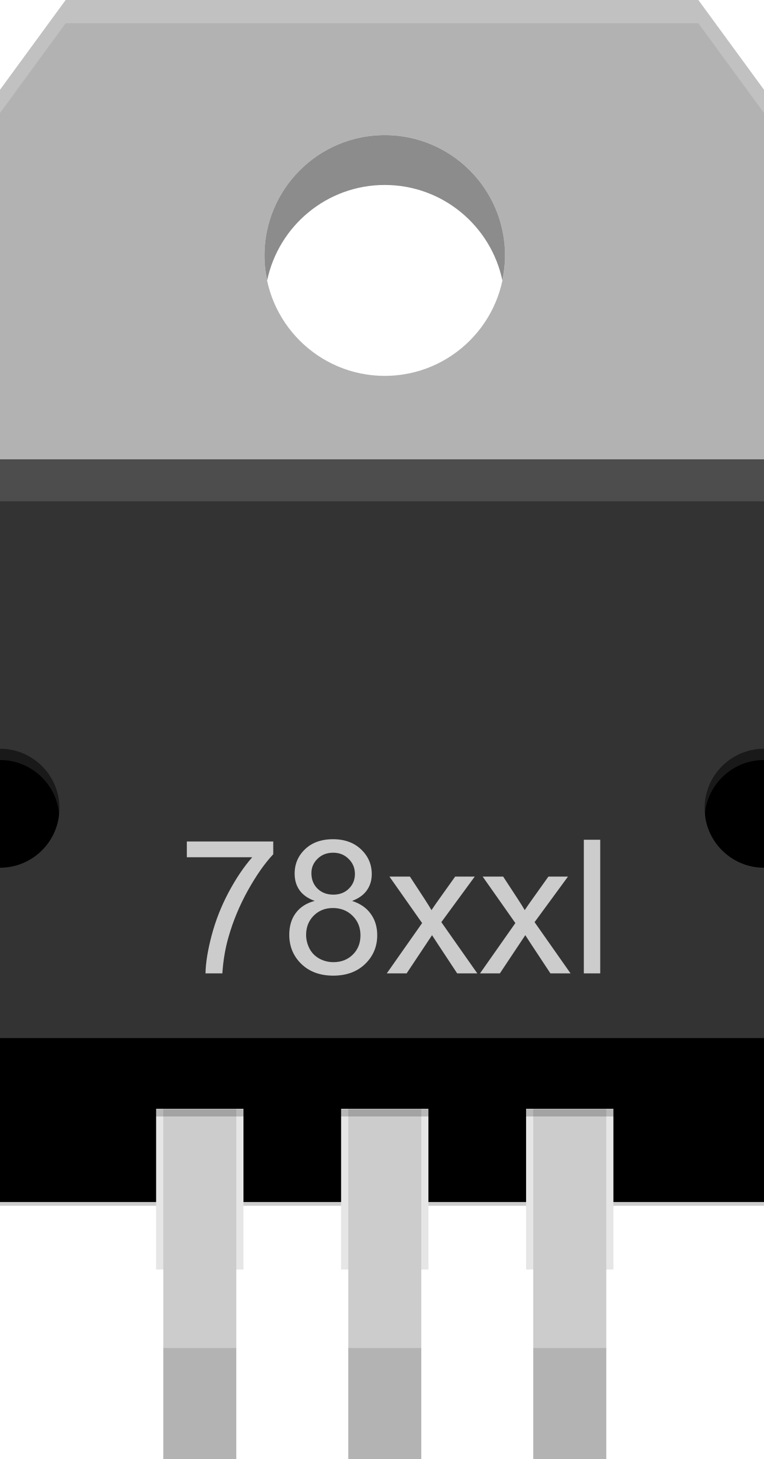
 Design with V_REG_LD1117VXX in Cirkit Designer
Introduction
The V_REG_LD1117VXX is a versatile, low-dropout (LDO) linear voltage regulator capable of providing a fixed output voltage with low power dissipation. This component is widely used in various electronic devices for power management, ensuring stable operation by maintaining a constant voltage level despite variations in input voltage and load conditions. Common applications include battery-powered devices, microcontroller power supplies, and peripheral power supplies.
Explore Projects Built with V_REG_LD1117VXX
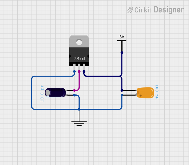
 Open Project in Cirkit Designer
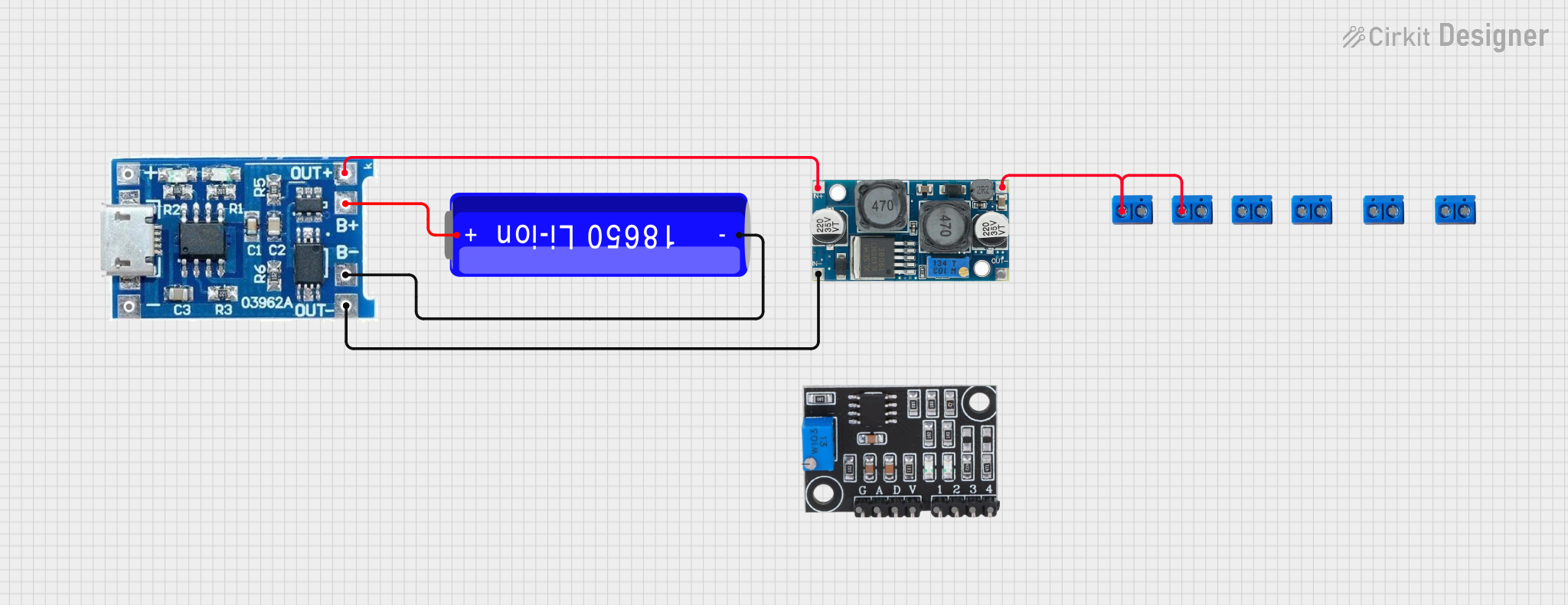
 Open Project in Cirkit Designer
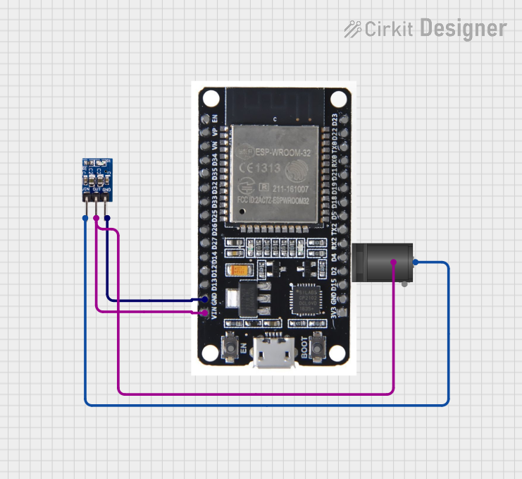
 Open Project in Cirkit Designer
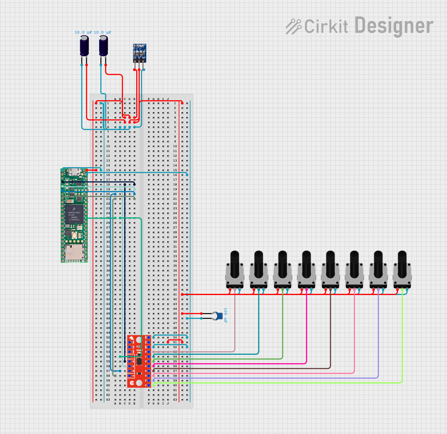
 Open Project in Cirkit Designer
Explore Projects Built with V_REG_LD1117VXX

 Open Project in Cirkit Designer
 Open Project in Cirkit Designer
 Open Project in Cirkit Designer
 Open Project in Cirkit Designer
Technical Specifications
Key Features
- Low dropout voltage
- Output voltage options: typically 1.8V, 2.5V, 3.3V, and 5V
- Output current: up to 800 mA
- Overcurrent and overtemperature protection
- Low quiescent current
Pin Configuration and Descriptions
| Pin Number | Name | Description |
|---|---|---|
| 1 | IN | Input voltage. Connect to the unregulated supply. |
| 2 | GND | Ground reference for the regulator. |
| 3 | OUT | Regulated output voltage. |
Usage Instructions
Incorporating into a Circuit
- Connect the input voltage (Vin) to the IN pin. Ensure that Vin exceeds the desired output voltage (Vout) by at least the dropout voltage specified in the datasheet, typically around 1V.
- Connect the GND pin to the system ground.
- The OUT pin provides the regulated voltage. Connect this to the load or the power input of the device requiring regulation.
Bypass Capacitors
To ensure stability and reduce noise, it is recommended to place a ceramic capacitor (typically 10 µF) between the IN pin and GND, and another ceramic capacitor (also typically 10 µF) between the OUT pin and GND, as close to the regulator as possible.
Heat Dissipation
The LD1117VXX can dissipate heat through its tab. If the regulator is expected to handle high loads, it may require a heatsink to prevent overheating.
Best Practices
- Avoid exceeding the maximum input voltage and current ratings.
- Use appropriate bypass capacitors to minimize voltage spikes.
- Ensure adequate heat sinking for thermal management.
- Keep the input and output capacitors as close to the regulator as possible.
Example Connection with Arduino UNO
// No specific code is required for the basic operation of the LD1117VXX
// as it is a hardware component. However, here is an example of how to
// connect it to an Arduino UNO to provide a regulated 5V supply.

// Arduino UNO 5V pin can be used as an input to the LD1117VXX if you
// want to regulate down to a lower voltage like 3.3V.

// Connect the LD1117VXX as follows:
// IN pin of LD1117VXX to 5V pin on Arduino UNO
// GND pin of LD1117VXX to GND on Arduino UNO
// OUT pin of LD1117VXX to any component requiring a regulated 3.3V

// Remember to add the bypass capacitors as mentioned in the Usage Instructions.
Troubleshooting and FAQs
Common Issues
- Output voltage is too low or unstable: Check if the input voltage is sufficient and the bypass capacitors are correctly installed.
- Regulator overheating: Ensure that the current draw is within the specified limit and that adequate heat sinking is provided.
- No output voltage: Verify the connections and ensure that the input voltage is present and within the specified range.
FAQs
Q: Can I use the LD1117VXX to step up voltage? A: No, the LD1117VXX is a linear regulator designed to step down voltage only.
Q: What is the maximum input voltage for the LD1117VXX? A: The maximum input voltage is typically around 15V, but you should always check the datasheet for the specific version of the LD1117VXX you are using.
Q: How can I improve the efficiency of my voltage regulator circuit? A: To improve efficiency, ensure that the input voltage is as close as possible to the output voltage to minimize the voltage drop and power dissipation.
Q: Is it necessary to use a heatsink with the LD1117VXX? A: It depends on the amount of current being drawn and the voltage difference between the input and output. If the regulator is dissipating a significant amount of power, a heatsink is recommended.
For further assistance or technical support, please refer to the manufacturer's datasheet or contact technical support.