How to Use FREENOVE ESP32-WROVER: Examples, Pinouts, and Specs
Introduction
The FREENOVE ESP32-WROVER is a powerful microcontroller module developed by Espressif. It features integrated Wi-Fi and Bluetooth capabilities, making it an excellent choice for Internet of Things (IoT) applications. With its dual-core processor, ample memory, and advanced connectivity options, the ESP32-WROVER is designed to handle complex tasks efficiently.
Explore Projects Built with FREENOVE ESP32-WROVER


Explore Projects Built with FREENOVE ESP32-WROVER
Common Applications and Use Cases
- IoT devices and smart home automation
- Wireless sensor networks
- Robotics and drones
- Wearable technology
- Industrial automation
- Real-time data monitoring and logging
- Prototyping and educational projects
Technical Specifications
The following table outlines the key technical details of the FREENOVE ESP32-WROVER module:
| Specification | Details |
|---|---|
| Microcontroller | ESP32-D0WDQ6 (dual-core Xtensa® 32-bit LX6 processor) |
| Clock Speed | Up to 240 MHz |
| Flash Memory | 4 MB (external) |
| PSRAM | 8 MB |
| Wi-Fi | 802.11 b/g/n (2.4 GHz) |
| Bluetooth | Bluetooth 4.2 (Classic and BLE) |
| Operating Voltage | 3.3V |
| Input Voltage Range | 3.0V to 3.6V |
| GPIO Pins | 36 |
| ADC Channels | 18 (12-bit resolution) |
| DAC Channels | 2 |
| Communication Interfaces | UART, SPI, I2C, I2S, CAN, PWM |
| Power Consumption | Ultra-low power consumption in deep sleep mode (as low as 10 µA) |
| Dimensions | 18 mm x 31 mm |
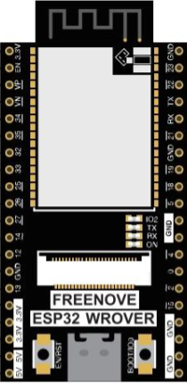
Pin Configuration and Descriptions
The ESP32-WROVER module has a variety of pins for different functionalities. Below is a table summarizing the key pins:
| Pin | Name | Description |
|---|---|---|
| 1 | GND | Ground pin |
| 2 | 3V3 | 3.3V power supply output |
| 3 | EN | Enable pin (active high) |
| 4 | IO0 | GPIO0, used for boot mode selection |
| 5 | IO2 | GPIO2, general-purpose I/O pin |
| 6 | IO4 | GPIO4, general-purpose I/O pin |
| 7 | IO5 | GPIO5, general-purpose I/O pin |
| 8 | IO12 | GPIO12, general-purpose I/O pin |
| 9 | IO13 | GPIO13, general-purpose I/O pin |
| 10 | IO14 | GPIO14, general-purpose I/O pin |
| 11 | IO15 | GPIO15, general-purpose I/O pin |
| 12 | IO16 | GPIO16, general-purpose I/O pin |
| 13 | IO17 | GPIO17, general-purpose I/O pin |
| 14 | IO18 | GPIO18, general-purpose I/O pin |
| 15 | IO19 | GPIO19, general-purpose I/O pin |
| 16 | IO21 | GPIO21, general-purpose I/O pin |
| 17 | IO22 | GPIO22, general-purpose I/O pin |
| 18 | IO23 | GPIO23, general-purpose I/O pin |
| 19 | IO25 | GPIO25, general-purpose I/O pin |
| 20 | IO26 | GPIO26, general-purpose I/O pin |
| 21 | IO27 | GPIO27, general-purpose I/O pin |
| 22 | IO32 | GPIO32, general-purpose I/O pin |
| 23 | IO33 | GPIO33, general-purpose I/O pin |
| 24 | IO34 | GPIO34, input-only pin |
| 25 | IO35 | GPIO35, input-only pin |
Usage Instructions
How to Use the Component in a Circuit
- Powering the Module: Connect the 3V3 pin to a 3.3V power source and the GND pin to ground.
- Programming the Module: Use a USB-to-serial adapter to connect the module to your computer. Ensure the EN pin is pulled high to enable the module.
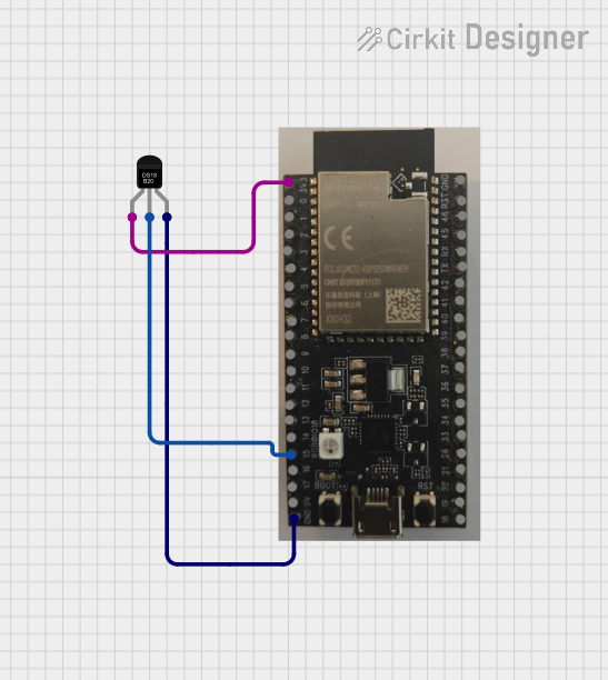
- Connecting Peripherals: Use the GPIO pins to interface with sensors, actuators, and other devices. Refer to the pin configuration table for specific pin functionalities.
- Wi-Fi and Bluetooth Setup: Use the ESP-IDF or Arduino IDE to configure the Wi-Fi and Bluetooth settings for your application.
Important Considerations and Best Practices
- Voltage Levels: Ensure all connected devices operate at 3.3V logic levels to avoid damaging the module.
- Deep Sleep Mode: Utilize the deep sleep mode to minimize power consumption in battery-powered applications.
- Antenna Placement: Avoid placing metal objects near the onboard antenna to ensure optimal wireless performance.
- Boot Mode: To enter bootloader mode for programming, hold the IO0 pin low while resetting the module.
Example Code for Arduino UNO
Below is an example of how to use the ESP32-WROVER with the Arduino IDE to connect to a Wi-Fi network:
#include <WiFi.h> // Include the Wi-Fi library

const char* ssid = "Your_SSID";       // Replace with your Wi-Fi network name
const char* password = "Your_PASSWORD"; // Replace with your Wi-Fi password

void setup() {
  Serial.begin(115200); // Initialize serial communication at 115200 baud
  delay(1000);          // Wait for a moment to stabilize

  Serial.println("Connecting to Wi-Fi...");
  WiFi.begin(ssid, password); // Start connecting to the Wi-Fi network

  while (WiFi.status() != WL_CONNECTED) {
    delay(500); // Wait for connection
    Serial.print(".");
  }

  Serial.println("\nConnected to Wi-Fi!");
  Serial.print("IP Address: ");
  Serial.println(WiFi.localIP()); // Print the assigned IP address
}

void loop() {
  // Add your main code here
}
Troubleshooting and FAQs
Common Issues Users Might Face
Module Not Powering On:
- Ensure the 3V3 pin is connected to a stable 3.3V power source.
- Check for loose or incorrect connections.
Wi-Fi Connection Fails:
- Verify the SSID and password are correct.
- Ensure the Wi-Fi network is within range and not overloaded.
Programming Errors:
- Ensure the correct COM port and board are selected in the Arduino IDE.
- Check that the IO0 pin is held low during programming.
Bluetooth Not Discoverable:
- Ensure Bluetooth is enabled in your code.
- Check for interference from other devices.
Solutions and Tips for Troubleshooting
- Use a multimeter to verify voltage levels at the power pins.
- Update the ESP32 core libraries in the Arduino IDE to the latest version.
- Refer to the Espressif documentation for advanced debugging techniques.
- Use serial debugging to monitor the module's output and identify issues.
By following this documentation, you can effectively integrate the FREENOVE ESP32-WROVER into your projects and troubleshoot common issues with ease.