Cirkit Designer Logo
Cirkit Designer
Your all-in-one circuit design IDE
Home / 
Component Documentation

How to Use PWR/GND Bus: Examples, Pinouts, and Specs

Image of PWR/GND Bus
Cirkit Designer LogoDesign with PWR/GND Bus in Cirkit Designer

Introduction

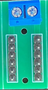
A PWR/GND Bus is a common electrical connection point in a circuit that distributes power (PWR) and ground (GND) connections to various components. It ensures a stable voltage supply and provides a common reference point for the circuit. This component is essential in simplifying circuit design, reducing wiring complexity, and maintaining consistent electrical performance.

Explore Projects Built with PWR/GND Bus

Use Cirkit Designer to design, explore, and prototype these projects online. Some projects support real-time simulation. Click "Open Project" to start designing instantly!
12V Multi-Component Control Circuit
Image of DEWX MOTOR 2: A project utilizing PWR/GND Bus in a practical application
This circuit appears to be a power distribution system that supplies power to various components from a 12V 5A power supply. It connects the negative terminal of the power supply to the ground (GND) pins of a mini diaphragm water pump, an RGB LED, a fan, and a water pump, while the positive DC output is connected to the positive pins of the RGB LED and presumably to other components through JST PH 2.0 connectors. The circuit lacks a controlling element, such as a microcontroller, suggesting that the components operate continuously or are switched externally.
Cirkit Designer LogoOpen Project in Cirkit Designer
24V Pushbutton Control Interface with 40-Pin Connector
Image of 4 på rad: A project utilizing PWR/GND Bus in a practical application
This circuit consists of a 24V power supply unit (PSU) connected to four pushbuttons. Each pushbutton is wired such that pressing it will send a 24V signal to a corresponding general-purpose input (GP In) on a 40-pin connector. The common return path for the pushbuttons is connected to the 0V of the PSU, which is also connected to the common (Com) for input pins on the 40-pin connector, completing the circuit for each button press.
Cirkit Designer LogoOpen Project in Cirkit Designer
Industrial Power Distribution and Safety Control System
Image of Control Diagram: A project utilizing PWR/GND Bus in a practical application
This circuit is designed for power distribution and safety control in an industrial setting. It features a main isolator and circuit breaker for power management, multiple PSUs for 5V, 12V, and 24V outputs, and a safety relay system that interfaces with E-stop buttons and a start switch to control a main contactor, ensuring safe operation and emergency power cut-off capabilities.
Cirkit Designer LogoOpen Project in Cirkit Designer
Dual 5V Power Supply Distribution Circuit with Toggle Switch Control
Image of rfdriver: A project utilizing PWR/GND Bus in a practical application
This circuit consists of two 5V 5A power supplies connected to an AC wall plug point, providing DC output through a 12-way connector. The ground connections from both power supplies are interconnected and also connected to the ground pins of two toggle switches. The DC outputs from the power supplies are separately connected to different pins on the 12-way connector, with each power supply output being switchable via one of the toggle switches.
Cirkit Designer LogoOpen Project in Cirkit Designer

Explore Projects Built with PWR/GND Bus

Use Cirkit Designer to design, explore, and prototype these projects online. Some projects support real-time simulation. Click "Open Project" to start designing instantly!
Image of DEWX MOTOR 2: A project utilizing PWR/GND Bus in a practical application
12V Multi-Component Control Circuit
This circuit appears to be a power distribution system that supplies power to various components from a 12V 5A power supply. It connects the negative terminal of the power supply to the ground (GND) pins of a mini diaphragm water pump, an RGB LED, a fan, and a water pump, while the positive DC output is connected to the positive pins of the RGB LED and presumably to other components through JST PH 2.0 connectors. The circuit lacks a controlling element, such as a microcontroller, suggesting that the components operate continuously or are switched externally.
Cirkit Designer LogoOpen Project in Cirkit Designer
Image of 4 på rad: A project utilizing PWR/GND Bus in a practical application
24V Pushbutton Control Interface with 40-Pin Connector
This circuit consists of a 24V power supply unit (PSU) connected to four pushbuttons. Each pushbutton is wired such that pressing it will send a 24V signal to a corresponding general-purpose input (GP In) on a 40-pin connector. The common return path for the pushbuttons is connected to the 0V of the PSU, which is also connected to the common (Com) for input pins on the 40-pin connector, completing the circuit for each button press.
Cirkit Designer LogoOpen Project in Cirkit Designer
Image of Control Diagram: A project utilizing PWR/GND Bus in a practical application
Industrial Power Distribution and Safety Control System
This circuit is designed for power distribution and safety control in an industrial setting. It features a main isolator and circuit breaker for power management, multiple PSUs for 5V, 12V, and 24V outputs, and a safety relay system that interfaces with E-stop buttons and a start switch to control a main contactor, ensuring safe operation and emergency power cut-off capabilities.
Cirkit Designer LogoOpen Project in Cirkit Designer
Image of rfdriver: A project utilizing PWR/GND Bus in a practical application
Dual 5V Power Supply Distribution Circuit with Toggle Switch Control
This circuit consists of two 5V 5A power supplies connected to an AC wall plug point, providing DC output through a 12-way connector. The ground connections from both power supplies are interconnected and also connected to the ground pins of two toggle switches. The DC outputs from the power supplies are separately connected to different pins on the 12-way connector, with each power supply output being switchable via one of the toggle switches.
Cirkit Designer LogoOpen Project in Cirkit Designer

Common Applications and Use Cases

  • Breadboard prototyping for distributing power and ground connections.
  • PCB designs to route power and ground to multiple components.
  • Power distribution in robotics, IoT devices, and embedded systems.
  • Ensuring stable voltage levels in high-current or high-frequency circuits.

Technical Specifications

The PWR/GND Bus itself does not have active electrical properties but is designed to handle specific voltage and current ratings based on its material and size. Below are typical specifications:

Parameter Specification
Voltage Rating Up to 50V (varies by design)
Current Rating 1A to 10A (depends on trace width/material)
Material Copper (with optional tin plating)
Insulation Resistance >100 MΩ
Operating Temperature -40°C to +85°C

Pin Configuration and Descriptions

The PWR/GND Bus typically consists of two main rails or strips:

Pin/Connection Description
PWR Rail (+) Positive voltage rail for power distribution.
GND Rail (-) Ground rail for providing a common reference.

Usage Instructions

How to Use the PWR/GND Bus in a Circuit

  1. Identify the Rails: Locate the PWR (+) and GND (-) rails on the bus. These are often color-coded (e.g., red for PWR and blue/black for GND).
  2. Connect Power Source: Attach the positive terminal of your power source to the PWR rail and the negative terminal to the GND rail.
  3. Distribute Connections: Connect the PWR and GND rails to the respective pins of your components or modules.
  4. Verify Connections: Double-check all connections to ensure proper polarity and avoid short circuits.

Important Considerations and Best Practices

  • Current Handling: Ensure the bus can handle the total current drawn by all connected components.
  • Voltage Drop: Minimize voltage drop by using a bus with low resistance and appropriate trace width.
  • Isolation: Avoid mixing different voltage levels on the same bus to prevent damage to components.
  • Decoupling Capacitors: Place decoupling capacitors near sensitive components to reduce noise and stabilize voltage.

Example: Using a PWR/GND Bus with an Arduino UNO

Below is an example of connecting an Arduino UNO to a PWR/GND Bus for powering external components like sensors or LEDs.

// Example: Powering an LED using a PWR/GND Bus with Arduino UNO

// Define the pin for the LED
const int ledPin = 9;

void setup() {
  pinMode(ledPin, OUTPUT); // Set the LED pin as an output
}

void loop() {
  digitalWrite(ledPin, HIGH); // Turn the LED on
  delay(1000);                // Wait for 1 second
  digitalWrite(ledPin, LOW);  // Turn the LED off
  delay(1000);                // Wait for 1 second
}

/*
 * Circuit Setup:
 * 1. Connect the Arduino UNO's 5V pin to the PWR rail of the bus.
 * 2. Connect the Arduino UNO's GND pin to the GND rail of the bus.
 * 3. Connect one terminal of the LED to the PWR rail via a 220-ohm resistor.
 * 4. Connect the other terminal of the LED to the Arduino's pin 9.
 */

Troubleshooting and FAQs

Common Issues Users Might Face

  1. No Power on the Bus:

    • Cause: Power source not connected or improperly connected.
    • Solution: Verify the power source connections to the PWR and GND rails.
  2. Voltage Drop Across the Bus:

    • Cause: Excessive current draw or insufficient trace width.
    • Solution: Use a bus with higher current capacity or reduce the load.
  3. Short Circuit:

    • Cause: Accidental connection between PWR and GND rails.
    • Solution: Inspect the bus for shorts and ensure proper insulation.
  4. Noise or Voltage Instability:

    • Cause: High-frequency noise or insufficient decoupling.
    • Solution: Add decoupling capacitors near sensitive components.

FAQs

Q: Can I use a PWR/GND Bus for multiple voltage levels?
A: It is not recommended to mix voltage levels on the same bus. Use separate buses for each voltage level to avoid damage to components.

Q: How do I calculate the required trace width for my bus?
A: Use an online PCB trace width calculator, considering the current and acceptable temperature rise.

Q: Can I use a PWR/GND Bus for AC circuits?
A: Yes, but ensure the bus is rated for the voltage and current of the AC circuit, and take proper safety precautions.

Q: What materials are commonly used for PWR/GND Buses?
A: Copper is the most common material, often with tin plating for improved conductivity and corrosion resistance.