
How to Use Power Module: Examples, Pinouts, and Specs
 Design with Power Module in Cirkit Designer
Introduction
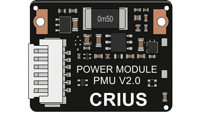
A power module is a versatile electronic component designed to supply electrical power to a circuit. It often integrates essential functions such as voltage regulation, power conversion, and protection features, ensuring stable and efficient operation. Power modules are widely used in various applications, including embedded systems, robotics, IoT devices, and industrial automation, where reliable power delivery is critical.
Common applications and use cases:
- Powering microcontrollers and development boards (e.g., Arduino, Raspberry Pi)
- Voltage regulation for sensors and actuators
- Battery-powered systems requiring step-up or step-down voltage conversion
- Industrial equipment requiring robust power management
Explore Projects Built with Power Module
 Open Project in Cirkit Designer
 Open Project in Cirkit Designer
 Open Project in Cirkit Designer
 Open Project in Cirkit Designer
Explore Projects Built with Power Module
Open Project in Cirkit DesignerOpen Project in Cirkit DesignerOpen Project in Cirkit DesignerOpen Project in Cirkit DesignerTechnical Specifications
Below are the general technical specifications for a typical power module. Note that specific models may vary, so always refer to the datasheet of your particular module.
Key Specifications
- Input Voltage Range: 4.5V to 28V (varies by model)
- Output Voltage Range: Adjustable (e.g., 3.3V, 5V, 12V)
- Output Current: Up to 3A (depending on the module)
- Efficiency: Up to 95% (depending on load and input/output conditions)
- Protection Features: Overcurrent, overvoltage, thermal shutdown, and short-circuit protection
- Operating Temperature: -40°C to +85°C
Pin Configuration and Descriptions
The pin configuration of a power module typically includes input, output, and ground connections. Below is an example of a common pinout:
| Pin Name | Description |
|---|---|
| VIN | Input voltage pin. Connect to the power source (e.g., battery or DC adapter). |
| GND | Ground pin. Connect to the ground of the circuit. |
| VOUT | Output voltage pin. Provides regulated voltage to the load. |
| ADJ (optional) | Adjustment pin. Used to set the output voltage (if adjustable). |
| EN (optional) | Enable pin. Used to turn the module on or off (active high or low, depending). |
Usage Instructions
How to Use the Power Module in a Circuit
- Connect the Input Voltage:
- Connect the VIN pin to your power source (e.g., a DC adapter or battery). Ensure the input voltage is within the module's specified range.
- Connect the Ground:
- Connect the GND pin to the ground of your circuit.
- Connect the Output Voltage:
- Connect the VOUT pin to the load or device you want to power. Ensure the load does not exceed the module's maximum current rating.
- Adjust the Output Voltage (if applicable):
- If the module has an ADJ pin or potentiometer, use it to set the desired output voltage. Use a multimeter to verify the output voltage before connecting the load.
- Enable the Module (if applicable):
- If the module has an EN pin, ensure it is properly configured (e.g., tied to VIN or GND) to enable the module.
Important Considerations and Best Practices
- Heat Dissipation: Power modules can generate heat under high loads. Ensure adequate ventilation or use a heatsink if necessary.
- Input Voltage Range: Always verify that the input voltage is within the module's specified range to avoid damage.
- Output Voltage Adjustment: When adjusting the output voltage, disconnect the load to prevent accidental overvoltage.
- Polarity: Double-check the polarity of your connections to avoid damaging the module or connected devices.
- Bypass Capacitors: Add bypass capacitors (e.g., 10µF and 0.1µF) near the input and output pins to improve stability and reduce noise.
Example: Using a Power Module with an Arduino UNO
Below is an example of how to use a power module to supply 5V to an Arduino UNO:
- Connect the VIN pin of the power module to a 9V battery.
- Connect the GND pin of the power module to the GND of the Arduino UNO.
- Connect the VOUT pin of the power module to the 5V pin of the Arduino UNO.
// Example Arduino code to blink an LED using a power module for power supply

const int ledPin = 13; // Pin connected to the onboard LED

void setup() {
  pinMode(ledPin, OUTPUT); // Set the LED pin as an output
}

void loop() {
  digitalWrite(ledPin, HIGH); // Turn the LED on
  delay(1000);                // Wait for 1 second
  digitalWrite(ledPin, LOW);  // Turn the LED off
  delay(1000);                // Wait for 1 second
}
Troubleshooting and FAQs
Common Issues and Solutions
No Output Voltage:
- Cause: Input voltage is too low or improperly connected.
- Solution: Verify the input voltage and connections. Ensure the EN pin is configured correctly (if applicable).
Overheating:
- Cause: Excessive load or poor ventilation.
- Solution: Reduce the load or add a heatsink to the module. Ensure proper airflow around the module.
Output Voltage Fluctuations:
- Cause: Insufficient bypass capacitors or unstable input voltage.
- Solution: Add bypass capacitors near the input and output pins. Use a stable power source.
Load Not Powering On:
- Cause: Output voltage is incorrectly set or load exceeds current rating.
- Solution: Verify the output voltage with a multimeter and ensure the load is within the module's current capacity.
FAQs
Can I use a power module to charge a battery?
- Some power modules support battery charging, but you must ensure the module is specifically designed for this purpose.
What happens if I exceed the input voltage range?
- Exceeding the input voltage range can damage the module. Always stay within the specified range.
Can I use a power module with AC input?
- No, power modules are designed for DC input only. Use an AC-to-DC adapter if your power source is AC.
By following these guidelines and best practices, you can effectively use a power module to power your electronic projects.