
How to Use 7 Segment Display - 13mm Common Cathode: Examples, Pinouts, and Specs
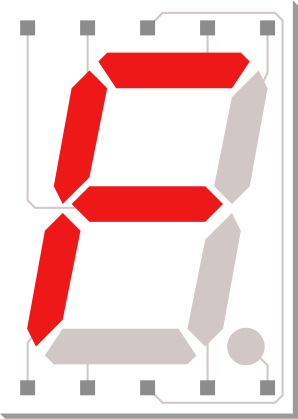
 Design with 7 Segment Display - 13mm Common Cathode in Cirkit Designer
Introduction
A 7-segment display is an electronic display device that uses seven individual LED segments arranged in a figure-eight pattern to represent decimal numbers and some letters. The 13mm Common Cathode variant is a popular choice for numeric displays due to its simplicity and ease of use. In the common cathode configuration, all the cathodes of the LED segments are connected together to a single ground pin, while the anodes are individually controlled to illuminate specific segments.
Explore Projects Built with 7 Segment Display - 13mm Common Cathode
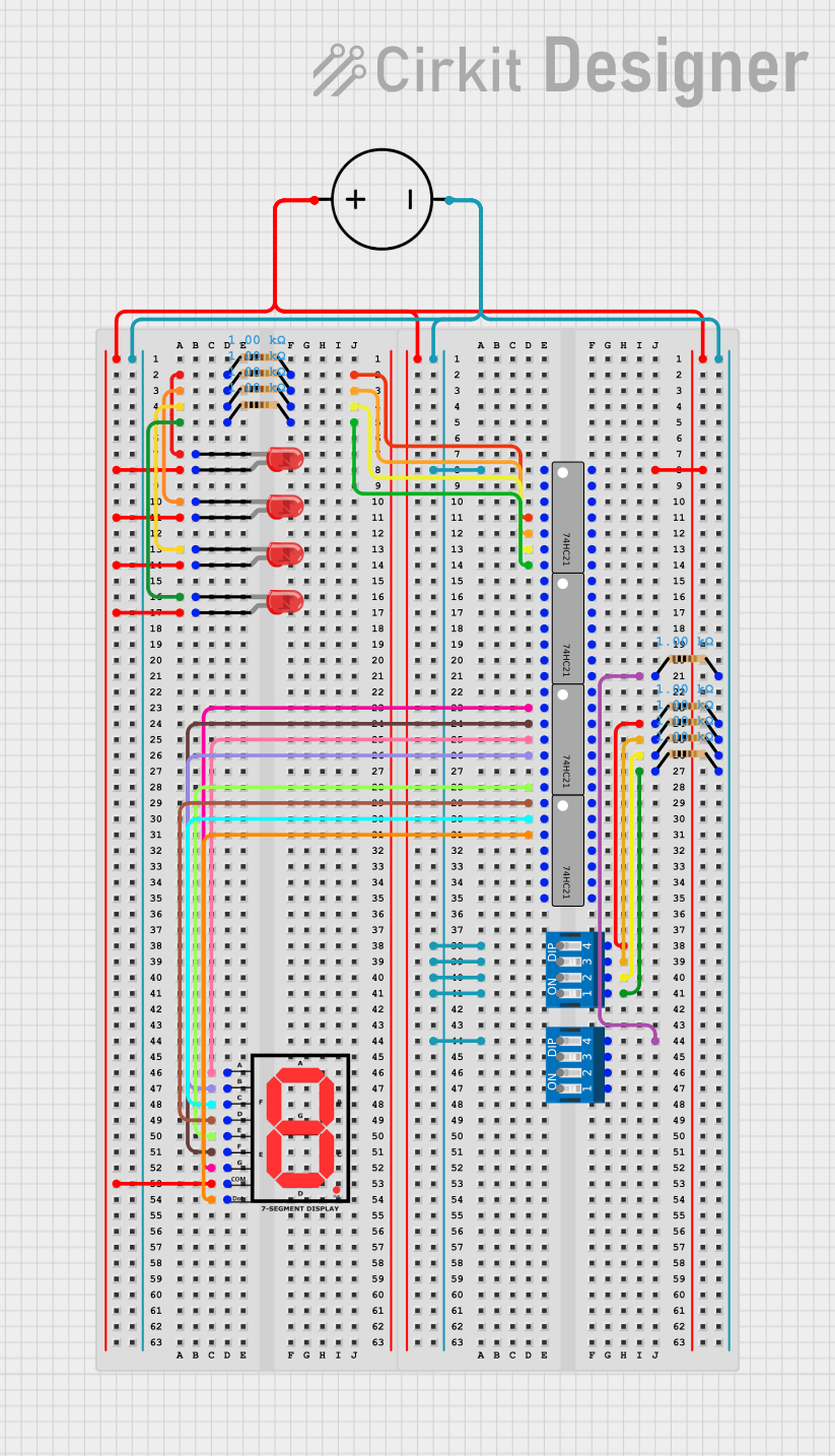 Open Project in Cirkit Designer
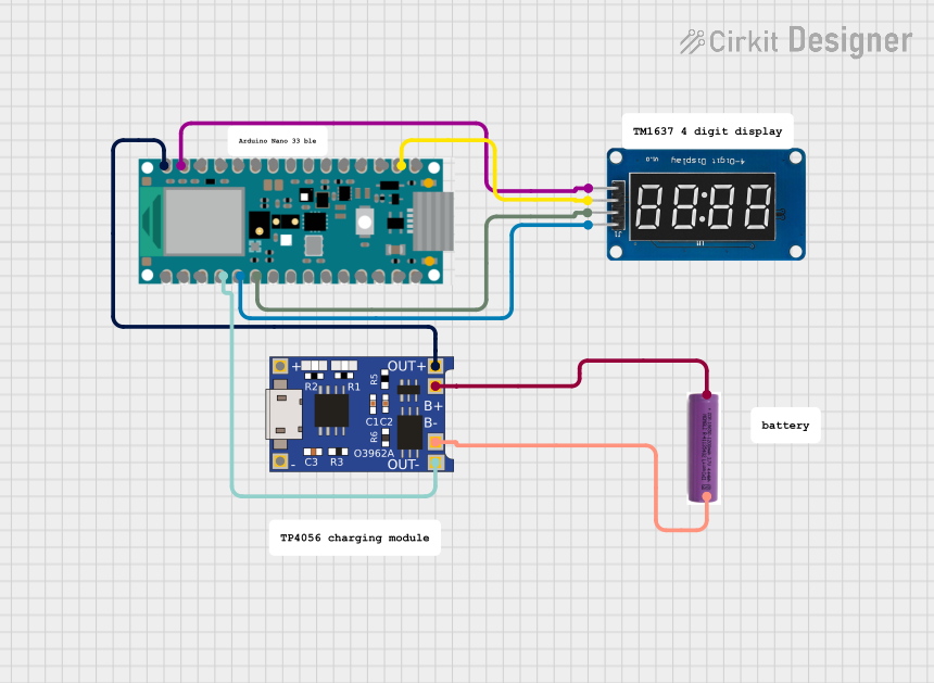 Open Project in Cirkit Designer
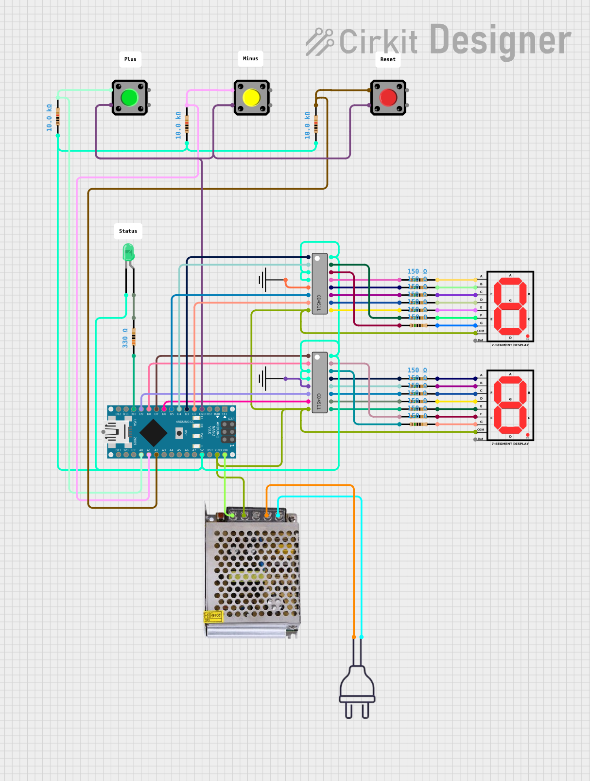 Open Project in Cirkit Designer
 Open Project in Cirkit Designer
Explore Projects Built with 7 Segment Display - 13mm Common Cathode
Open Project in Cirkit DesignerOpen Project in Cirkit DesignerOpen Project in Cirkit DesignerOpen Project in Cirkit DesignerCommon Applications and Use Cases
- Digital clocks and timers
- Electronic meters and counters
- Temperature and humidity displays
- Simple numeric displays in embedded systems
- Educational projects and prototyping
Technical Specifications
Key Technical Details
- Display Type: 7-segment LED display
- Configuration: Common Cathode
- Digit Height: 13mm (0.51 inches)
- Operating Voltage: Typically 2V per segment (varies slightly by color)
- Forward Current: 10-20mA per segment (maximum 30mA)
- Common Cathode Pin: Connects to ground (GND)
- Segment Control: Positive voltage applied to individual anode pins
- Typical Colors: Red, green, or blue (depending on the model)
- Viewing Angle: ~120 degrees
- Operating Temperature: -40°C to +85°C
Pin Configuration and Descriptions
The 7-segment display has 10 pins, with each pin corresponding to a specific segment or the common cathode. Below is the pinout for a standard 13mm Common Cathode 7-segment display:
| Pin Number | Segment/Function | Description |
|---|---|---|
| 1 | E | Controls segment E |
| 2 | D | Controls segment D |
| 3 | Common Cathode (CC) | Connects to ground (GND) |
| 4 | C | Controls segment C |
| 5 | Decimal Point (DP) | Controls the decimal point (if available) |
| 6 | B | Controls segment B |
| 7 | A | Controls segment A |
| 8 | Common Cathode (CC) | Connects to ground (GND) |
| 9 | F | Controls segment F |
| 10 | G | Controls segment G |
Segment Layout
The segments are labeled as follows for reference:
  --A--
 |     |
 F     B
 |     |
  --G--
 |     |
 E     C
 |     |
  --D--   (DP)
Usage Instructions
How to Use the Component in a Circuit
- Connect the Common Cathode: Connect one of the common cathode pins (Pin 3 or Pin 8) to the ground (GND) of your circuit.
- Control the Segments: Apply a positive voltage to the anode pins (A, B, C, D, E, F, G, and DP) to illuminate the corresponding segments.
- Use Current-Limiting Resistors: Place a resistor (typically 220Ω to 1kΩ) in series with each segment to limit the current and prevent damage to the LEDs.
- Drive the Display: Use a microcontroller (e.g., Arduino UNO) or a driver IC (e.g., 74HC595 shift register) to control the segments programmatically.
Important Considerations and Best Practices
- Current Limiting: Always use resistors to limit the current through each segment.
- Power Supply: Ensure the power supply voltage matches the forward voltage of the LEDs.
- Brightness Control: Use pulse-width modulation (PWM) to adjust the brightness of the display.
- Avoid Overdriving: Do not exceed the maximum current rating of 30mA per segment.
- Multiplexing: For multi-digit displays, consider using multiplexing to reduce the number of control pins required.
Example: Connecting to an Arduino UNO
Below is an example of how to connect and control a single 7-segment display with an Arduino UNO:
Circuit Connections
- Connect Pin 3 (Common Cathode) to GND.
- Connect Pins 1, 2, 4, 5, 6, 7, 9, and 10 to Arduino digital pins via 220Ω resistors.
- Use the following pin mapping for the Arduino:
| Segment | 7-Segment Pin | Arduino Pin |
|---|---|---|
| A | 7 | 2 |
| B | 6 | 3 |
| C | 4 | 4 |
| D | 2 | 5 |
| E | 1 | 6 |
| F | 9 | 7 |
| G | 10 | 8 |
| DP | 5 | 9 |
Arduino Code Example
// Arduino code to display the number "8" on a 7-segment display

// Define the Arduino pins connected to each segment
const int segmentPins[] = {2, 3, 4, 5, 6, 7, 8, 9}; // A, B, C, D, E, F, G, DP

// Segment states for displaying the number "8"
// 1 = ON, 0 = OFF
const int number8[] = {1, 1, 1, 1, 1, 1, 1, 0}; // DP is OFF

void setup() {
  // Set all segment pins as OUTPUT
  for (int i = 0; i < 8; i++) {
    pinMode(segmentPins[i], OUTPUT);
  }
}

void loop() {
  // Display the number "8"
  for (int i = 0; i < 8; i++) {
    digitalWrite(segmentPins[i], number8[i]);
  }
  delay(1000); // Keep the number displayed for 1 second
}
Troubleshooting and FAQs
Common Issues and Solutions
Segments Not Lighting Up:
- Check the connections to the common cathode pin (ensure it is connected to GND).
- Verify that the resistors are properly connected and not open-circuited.
- Ensure the Arduino or power supply is providing sufficient voltage.
Dim or Uneven Brightness:
- Use resistors of the same value for all segments to ensure uniform brightness.
- Check the power supply voltage and current capacity.
Overheating:
- Ensure the current through each segment does not exceed 20mA.
- Use appropriate resistors to limit the current.
Incorrect Display Output:
- Verify the pin mapping between the Arduino and the 7-segment display.
- Check the code logic to ensure the correct segments are being activated.
FAQs
Q: Can I control multiple 7-segment displays with an Arduino?
A: Yes, you can use multiplexing or a driver IC like the MAX7219 to control multiple displays with fewer pins.
Q: What resistor value should I use?
A: A 220Ω resistor is a common choice, but you can calculate the exact value using Ohm's Law:
( R = \frac{V_{supply} - V_{forward}}{I_{forward}} )
Q: Can I use this display with a 3.3V microcontroller?
A: Yes, but ensure the forward voltage of the LEDs is compatible with the 3.3V supply. Use appropriate resistors to limit the current.