How to Use Nano 33 BLE with pinout: Examples, Pinouts, and Specs
Introduction
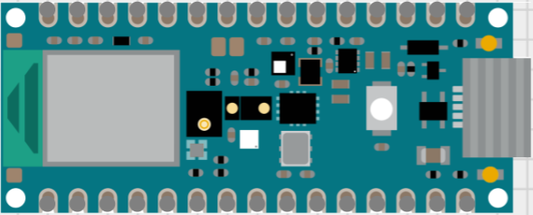
The Arduino Nano 33 BLE is a compact and feature-rich development board based on the Nordic nRF52840 microcontroller. It is designed for projects that require Bluetooth connectivity and low-power features. The board is ideal for wearable devices, smart home applications, and IoT projects due to its small form factor and powerful processor, which includes an ARM Cortex-M4 CPU with floating-point unit (FPU).
Explore Projects Built with Nano 33 BLE with pinout
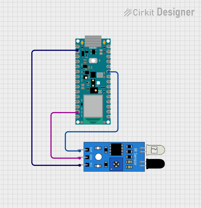

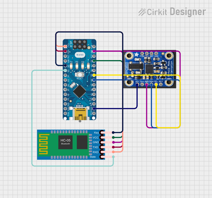
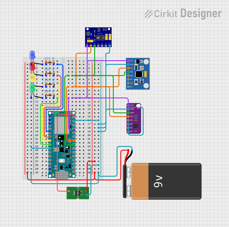
Explore Projects Built with Nano 33 BLE with pinout
Technical Specifications
Key Technical Details
- Microcontroller: Nordic nRF52840
- Operating Voltage: 3.3V
- Input Voltage (VIN): 4.5V - 21V
- Digital I/O Pins: 14
- PWM Pins: All digital pins
- Analog Input Pins: 8
- Analog Output Pins: None (DAC not included)
- DC Current per I/O Pin: 15 mA
- Flash Memory: 1 MB
- SRAM: 256 KB
- Clock Speed: 64 MHz
- Bluetooth: BLE 5.0
Pin Configuration and Descriptions
| Pin Number | Function | Description |
|---|---|---|
| D0-D13 | Digital I/O | Digital input/output, PWM output on most pins |
| A0-A7 | Analog Input | Analog input pins, 12-bit ADC resolution |
| 5V | Voltage Output | Regulated 5V output (derived from VIN) |
| 3.3V | Voltage Output | Regulated 3.3V output, 50 mA max |
| GND | Ground | Ground pins |
| VIN | Voltage Input | Unregulated input voltage to power the board |
| RST | Reset | Active low reset input |
| TX0, RX0 | Serial | UART communication |
| SDA, SCL | I2C | I2C communication pins |
| MISO, MOSI, SCK | SPI | SPI communication pins |
Usage Instructions
Integrating with a Circuit
To use the Nano 33 BLE in a circuit:
- Connect the VIN pin to a power supply between 4.5V and 21V, or plug in the board via USB.
- Connect the GND pin to the ground of your power supply.
- Utilize digital and analog pins as required for your project, ensuring you do not exceed the maximum current rating of 15 mA per I/O pin.
Best Practices
- Always disconnect the board from power sources before making or altering connections.
- Use a current limiting resistor with LEDs and other sensitive components.
- Avoid exposing the board to static electricity or physical shocks.
- When using Bluetooth functionality, ensure compliance with local regulations regarding wireless communication.
Example Code for Arduino UNO
Here is a simple example code that blinks the onboard LED connected to pin D13. This code can be used to test the board's functionality.
// Pin 13 has an LED connected on most Arduino boards.
int ledPin = 13;

// The setup routine runs once when you press reset:
void setup() {
  // Initialize the digital pin as an output.
  pinMode(ledPin, OUTPUT);
}

// The loop routine runs over and over again forever:
void loop() {
  digitalWrite(ledPin, HIGH);   // Turn the LED on (HIGH is the voltage level)
  delay(1000);                  // Wait for a second
  digitalWrite(ledPin, LOW);    // Turn the LED off by making the voltage LOW
  delay(1000);                  // Wait for a second
}
Troubleshooting and FAQs
Common Issues
- Board not recognized: Ensure the USB cable is properly connected and the computer has the necessary drivers installed.
- Sketch not uploading: Check the selected board and port in the Arduino IDE. Ensure the bootloader is functioning correctly.
- Bluetooth not working: Verify that the BLE code is correct and that the device you are trying to connect to is BLE compatible.
Solutions and Tips
- If the board is not recognized, try a different USB cable or port.
- For upload issues, double-check the connections and ensure no other program is using the same COM port.
- For Bluetooth issues, ensure that the antenna area of the board is not obstructed.
FAQs
Q: Can I power the Nano 33 BLE with 5V? A: It is recommended to power the board with a voltage between 4.5V and 21V on the VIN pin. The board can also be powered via the USB connection.
Q: Is the Nano 33 BLE compatible with all Arduino libraries? A: Most libraries that do not depend on AVR-specific hardware should work. Libraries that are designed for specific hardware may need modifications.
Q: How do I reset the board? A: You can reset the board by briefly connecting the RST pin to GND or by pressing the onboard reset button.
Remember to always consult the official Arduino Nano 33 BLE documentation for the most up-to-date and detailed information.