
How to Use ISD1820: Examples, Pinouts, and Specs
 Design with ISD1820 in Cirkit Designer
Introduction
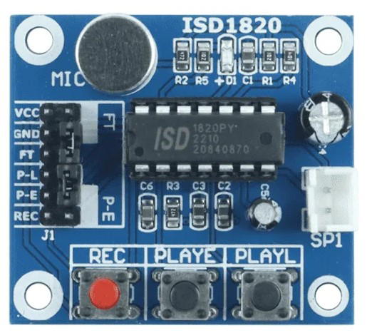
The ISD1820 is a voice recording and playback integrated circuit (IC) designed for simple and efficient audio message storage and playback. It allows users to record audio messages directly onto the chip and play them back with minimal external components. The ISD1820 is widely used in applications such as toys, greeting cards, voice reminders, and other audio playback devices. Its ease of use and compact design make it a popular choice for hobbyists and professionals alike.
Explore Projects Built with ISD1820
 Open Project in Cirkit Designer
 Open Project in Cirkit Designer
 Open Project in Cirkit Designer
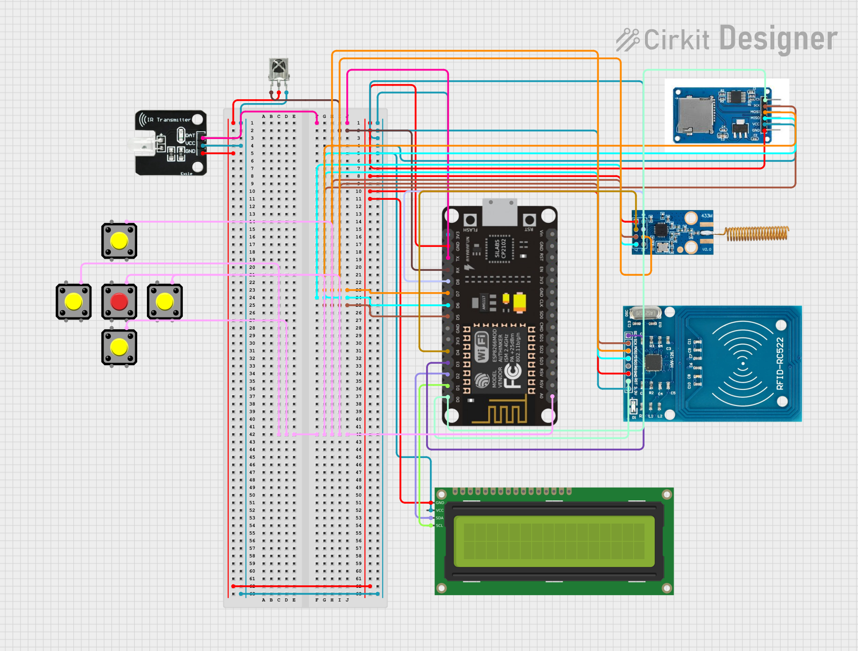 Open Project in Cirkit Designer
Explore Projects Built with ISD1820
Open Project in Cirkit DesignerOpen Project in Cirkit DesignerOpen Project in Cirkit DesignerOpen Project in Cirkit DesignerTechnical Specifications
The ISD1820 offers the following key technical features:
- Operating Voltage: 2.4V to 5.5V DC
- Recording Duration: 8 to 20 seconds (adjustable via an external resistor)
- Audio Storage: Non-volatile memory (retains audio even without power)
- Playback Modes: Edge-triggered playback, level-hold playback, and looping playback
- Microphone Input: Built-in preamplifier for direct microphone connection
- Speaker Output: Supports direct connection to an 8Ω speaker
- Dimensions: Compact DIP-14 package
Pin Configuration and Descriptions
The ISD1820 IC has 14 pins, each with specific functions. The table below provides a detailed description of each pin:
| Pin Number | Pin Name | Description |
|---|---|---|
| 1 | VCC | Power supply input (2.4V to 5.5V DC). |
| 2 | REC | Active-high input for recording audio. |
| 3 | PLAYE | Edge-triggered playback input. Plays the recorded message once per trigger. |
| 4 | PLAYL | Level-hold playback input. Plays the message as long as the pin is held high. |
| 5 | FT | Feed-through mode. Passes microphone input directly to the speaker output. |
| 6 | MIC+ | Positive terminal for the microphone input. |
| 7 | MIC- | Negative terminal for the microphone input. |
| 8 | AGC | Automatic Gain Control pin for microphone input. |
| 9 | SP+ | Positive terminal for speaker output. |
| 10 | SP- | Negative terminal for speaker output. |
| 11 | VSS | Ground connection. |
| 12 | NC | No connection (not used). |
| 13 | ROSC | External resistor pin to set the recording duration. |
| 14 | NC | No connection (not used). |
Usage Instructions
How to Use the ISD1820 in a Circuit
- Power Supply: Connect the VCC pin to a 3.3V or 5V DC power source and the VSS pin to ground.
- Microphone Connection: Attach an electret microphone to the MIC+ and MIC- pins. Optionally, connect a capacitor (e.g., 0.1µF) across these pins for noise filtering.
- Speaker Connection: Connect an 8Ω speaker to the SP+ and SP- pins for audio output.
- Recording Audio:
- Pull the REC pin high to start recording. The chip will record audio from the microphone.
- Release the REC pin to stop recording.
- Playback Audio:
- Use the PLAYE pin for edge-triggered playback. A single high pulse will play the recorded message once.
- Use the PLAYL pin for level-hold playback. The message will play as long as the pin is held high.
- Feed-Through Mode: Pull the FT pin high to directly route the microphone input to the speaker output.
Important Considerations and Best Practices
- Use a resistor on the ROSC pin to adjust the recording duration. For example:
- 100kΩ resistor: ~10 seconds recording time.
- 200kΩ resistor: ~20 seconds recording time.
- Ensure the power supply is stable and within the specified voltage range to avoid distortion or malfunction.
- Avoid excessive noise near the microphone to ensure clear audio recording.
- Use decoupling capacitors (e.g., 0.1µF) near the VCC pin to reduce power supply noise.
Example: Connecting ISD1820 to Arduino UNO
The ISD1820 can be easily interfaced with an Arduino UNO for automated control. Below is an example code snippet to record and play audio using the ISD1820:
// Define pin connections for ISD1820
const int recPin = 7;    // Connect to REC pin of ISD1820
const int playePin = 8;  // Connect to PLAYE pin of ISD1820

void setup() {
  pinMode(recPin, OUTPUT);   // Set REC pin as output
  pinMode(playePin, OUTPUT); // Set PLAYE pin as output
}

void loop() {
  // Record audio for 5 seconds
  digitalWrite(recPin, HIGH); // Start recording
  delay(5000);                // Record for 5 seconds
  digitalWrite(recPin, LOW);  // Stop recording

  delay(2000); // Wait for 2 seconds before playback

  // Play the recorded audio
  digitalWrite(playePin, HIGH); // Trigger playback
  delay(100);                   // Short delay to ensure trigger
  digitalWrite(playePin, LOW);  // Stop playback trigger

  delay(5000); // Wait before repeating the process
}
Troubleshooting and FAQs
Common Issues and Solutions
No Audio Playback:
- Ensure the REC pin was properly triggered during recording.
- Verify the speaker connections to SP+ and SP-.
- Check the power supply voltage (2.4V to 5.5V DC).
Distorted Audio:
- Reduce background noise during recording.
- Use a stable power supply with proper decoupling capacitors.
- Verify the microphone is functioning correctly.
Playback Not Triggering:
- Confirm the PLAYE or PLAYL pin is being properly triggered.
- Check for loose or incorrect connections.
Short Recording Duration:
- Adjust the resistor on the ROSC pin to increase the recording time.
FAQs
Q1: Can I use a different speaker impedance?
A1: The ISD1820 is optimized for an 8Ω speaker. Using a different impedance may affect audio quality.
Q2: Does the ISD1820 retain audio after power is removed?
A2: Yes, the ISD1820 uses non-volatile memory to store audio, so the message is retained even without power.
Q3: Can I record and play audio simultaneously?
A3: No, the ISD1820 does not support simultaneous recording and playback.
Q4: How can I extend the recording duration?
A4: Increase the resistance of the external resistor connected to the ROSC pin. Note that longer durations may reduce audio quality.
By following this documentation, users can effectively utilize the ISD1820 for various audio recording and playback applications.