
How to Use d95: Examples, Pinouts, and Specs
 Design with d95 in Cirkit Designer
Introduction
The D95 is a high-performance diode designed primarily for rectification in power supply circuits. It is a unidirectional component that allows current to flow in one direction while blocking it in the opposite direction. This property makes it an essential component in converting alternating current (AC) to direct current (DC). The D95 diode is known for its reliability, efficiency, and ability to handle high current loads, making it suitable for a wide range of applications.
Explore Projects Built with d95
 Open Project in Cirkit Designer
 Open Project in Cirkit Designer
 Open Project in Cirkit Designer
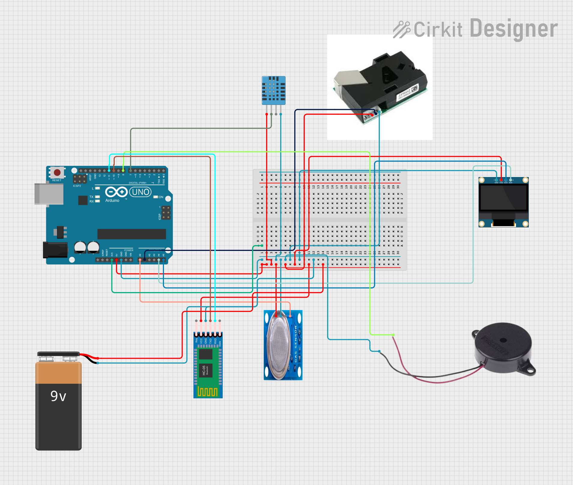
 Open Project in Cirkit Designer
Explore Projects Built with d95

 Open Project in Cirkit Designer
 Open Project in Cirkit Designer
 Open Project in Cirkit Designer
 Open Project in Cirkit Designer
Common Applications and Use Cases
- Rectification in AC-to-DC power supplies
- Freewheeling diodes in inductive circuits
- Protection against reverse polarity in electronic circuits
- Voltage clamping and surge protection
- Used in motor control and industrial power systems
Technical Specifications
The D95 diode is designed to handle high current and voltage ratings, making it ideal for power electronics. Below are its key technical specifications:
| Parameter | Value |
|---|---|
| Maximum Reverse Voltage (VR) | 1000 V |
| Maximum Forward Current (IF) | 10 A |
| Peak Surge Current (IFSM) | 150 A |
| Forward Voltage Drop (VF) | 1.1 V (at 10 A) |
| Reverse Recovery Time (trr) | 2 µs |
| Operating Temperature Range | -55°C to +150°C |
| Package Type | DO-201 or similar axial lead |
Pin Configuration and Descriptions
The D95 diode has a simple two-terminal configuration:
| Pin | Name | Description |
|---|---|---|
| 1 | Anode (A) | Positive terminal; current enters through this pin. |
| 2 | Cathode (K) | Negative terminal; current exits through this pin. |
The cathode is typically marked with a band or stripe on the diode body for easy identification.
Usage Instructions
How to Use the D95 Diode in a Circuit
- Identify the Terminals: Locate the anode and cathode. The cathode is marked with a stripe.
- Connect in the Correct Orientation: Ensure the anode is connected to the positive side of the circuit and the cathode to the negative side.
- Use in Rectification: For AC-to-DC conversion, use the D95 diode in a rectifier configuration (e.g., half-wave or full-wave rectifier).
- Add a Heat Sink if Necessary: If the diode is operating near its maximum current rating, consider using a heat sink to dissipate heat and prevent thermal damage.
- Include a Snubber Circuit: In high-frequency or inductive applications, use a snubber circuit to protect the diode from voltage spikes.
Important Considerations and Best Practices
- Current Rating: Do not exceed the maximum forward current (10 A) to avoid overheating or damage.
- Reverse Voltage: Ensure the reverse voltage in the circuit does not exceed 1000 V.
- Thermal Management: Operate the diode within its specified temperature range and provide adequate cooling if necessary.
- Polarity: Double-check the orientation of the diode before powering the circuit to prevent reverse polarity issues.
Example: Using the D95 Diode with an Arduino UNO
The D95 diode can be used in conjunction with an Arduino UNO for applications such as motor control or reverse polarity protection. Below is an example of using the D95 diode in a motor control circuit:
/*
  Example: Using the D95 Diode for Motor Protection
  This circuit demonstrates how to use the D95 diode as a freewheeling diode
  to protect the motor driver and Arduino from voltage spikes caused by
  inductive loads.

  Components:
  - Arduino UNO
  - D95 Diode
  - DC Motor
  - Motor Driver (e.g., L298N)
*/

void setup() {
  // Initialize motor control pins
  pinMode(9, OUTPUT); // Motor control pin 1
  pinMode(10, OUTPUT); // Motor control pin 2
}

void loop() {
  // Rotate motor in one direction
  digitalWrite(9, HIGH); // Set pin 9 HIGH
  digitalWrite(10, LOW); // Set pin 10 LOW
  delay(2000); // Run motor for 2 seconds

  // Rotate motor in the opposite direction
  digitalWrite(9, LOW); // Set pin 9 LOW
  digitalWrite(10, HIGH); // Set pin 10 HIGH
  delay(2000); // Run motor for 2 seconds
}
In this example, the D95 diode is connected across the motor terminals with the cathode connected to the positive terminal. This configuration prevents voltage spikes from damaging the motor driver or Arduino.
Troubleshooting and FAQs
Common Issues and Solutions
Diode Overheating
- Cause: Exceeding the maximum forward current or insufficient cooling.
- Solution: Reduce the current load or add a heat sink to dissipate heat.
Reverse Voltage Breakdown
- Cause: Reverse voltage exceeds the maximum rating (1000 V).
- Solution: Ensure the circuit's reverse voltage is within the diode's specifications.
Incorrect Polarity
- Cause: The diode is connected in the wrong orientation.
- Solution: Verify the anode and cathode connections before powering the circuit.
Low Efficiency in High-Frequency Applications
- Cause: The diode's reverse recovery time (2 µs) may not be suitable for high-frequency circuits.
- Solution: Use a fast recovery or Schottky diode for high-frequency applications.
FAQs
Q: Can the D95 diode be used in high-frequency circuits?
A: The D95 diode has a reverse recovery time of 2 µs, which may not be ideal for high-frequency applications. Consider using a fast recovery or Schottky diode for such cases.
Q: How do I identify the cathode of the D95 diode?
A: The cathode is marked with a stripe or band on the diode body.
Q: What happens if I exceed the diode's maximum current rating?
A: Exceeding the current rating can cause the diode to overheat, potentially leading to failure or permanent damage.
Q: Can I use the D95 diode for surge protection?
A: Yes, the D95 diode can be used for surge protection, but ensure the surge current does not exceed its peak surge current rating (150 A).