How to Use 3.5 In TFT Display Module: Examples, Pinouts, and Specs
Introduction
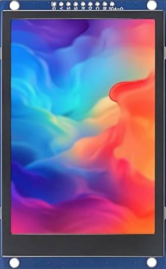
The 3.5 In TFT Display Module (Manufacturer Part ID: 3.5TFT-03-SPI-16P-8P-St7769_LCM) by Estar Dyn is a high-resolution, full-color display designed for use in embedded systems and portable devices. This module features a 3.5-inch thin-film transistor (TFT) screen, capable of rendering vibrant graphics and text. It is equipped with the ST7769 driver IC, which supports SPI communication for efficient data transfer.
Explore Projects Built with 3.5 In TFT Display Module


Explore Projects Built with 3.5 In TFT Display Module
Common Applications
- Portable devices such as handheld consoles and smart appliances
- Embedded systems requiring graphical user interfaces (GUIs)
- Industrial control panels and instrumentation displays
- Educational and hobbyist projects using microcontrollers like Arduino or Raspberry Pi
Technical Specifications
Key Technical Details
| Parameter | Specification |
|---|---|
| Display Size | 3.5 inches |
| Resolution | 320 x 480 pixels (HVGA) |
| Display Type | TFT (Thin-Film Transistor) |
| Driver IC | ST7769 |
| Interface | SPI (Serial Peripheral Interface) |
| Operating Voltage | 3.3V |
| Backlight Voltage | 3.0V to 3.6V |
| Backlight Current | 20mA to 40mA |
| Viewing Angle | 160° |
| Operating Temperature | -20°C to 70°C |
| Storage Temperature | -30°C to 80°C |
Pin Configuration
The module has two connectors: a 16-pin interface for the main display signals and an 8-pin backlight connector. Below is the pin configuration:
16-Pin Interface
| Pin No. | Name | Description |
|---|---|---|
| 1 | GND | Ground |
| 2 | VCC | Power supply (3.3V) |
| 3 | CS | Chip Select (active low) |
| 4 | RESET | Reset signal (active low) |
| 5 | DC | Data/Command control |
| 6 | SDI | Serial Data Input (MOSI) |
| 7 | SCK | Serial Clock |
| 8 | LED+ | Backlight positive |
| 9 | LED- | Backlight negative |
| 10-16 | NC | Not connected |
8-Pin Backlight Connector
| Pin No. | Name | Description |
|---|---|---|
| 1 | LED+ | Backlight positive |
| 2 | LED- | Backlight negative |
| 3-8 | NC | Not connected |
Usage Instructions
Connecting the Display to an Arduino UNO
To use the 3.5 In TFT Display Module with an Arduino UNO, follow these steps:
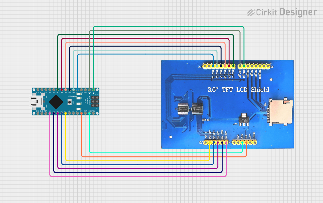
Wiring the Module:
- Connect the GND pin of the display to the Arduino's GND.
- Connect the VCC pin of the display to the Arduino's 3.3V pin.
- Connect the CS pin to Arduino digital pin 10.
- Connect the RESET pin to Arduino digital pin 9.
- Connect the DC pin to Arduino digital pin 8.
- Connect the SDI pin to Arduino digital pin 11 (MOSI).
- Connect the SCK pin to Arduino digital pin 13 (SCK).
- Connect the LED+ and LED- pins to a 3.3V power source for the backlight.
Install Required Libraries:
- Install the Adafruit GFX Library and Adafruit ST7789 Library (compatible with ST7769) from the Arduino Library Manager.
Upload Example Code: Use the following example code to initialize the display and draw basic graphics:
#include <Adafruit_GFX.h>       // Core graphics library
#include <Adafruit_ST7789.h>    // ST7789 driver (compatible with ST7769)
// Define pins for SPI communication #define TFT_CS 10 // Chip Select pin #define TFT_RST 9 // Reset pin #define TFT_DC 8 // Data/Command pin
// Create an instance of the display Adafruit_ST7789 tft = Adafruit_ST7789(TFT_CS, TFT_DC, TFT_RST);
void setup() { // Initialize the display tft.init(320, 480); // Initialize with resolution 320x480 tft.setRotation(1); // Set display orientation (1 = landscape)
// Fill the screen with a color tft.fillScreen(ST77XX_BLUE);
// Draw a rectangle tft.fillRect(50, 50, 100, 100, ST77XX_RED);
// Display text tft.setTextColor(ST77XX_WHITE); tft.setTextSize(2); tft.setCursor(10, 10); tft.print("Hello, TFT!"); }
void loop() { // No actions in the loop }
Important Considerations
- Voltage Levels: Ensure the module operates at 3.3V. Using 5V may damage the display.
- Backlight Power: Use a current-limiting resistor if the backlight is powered directly from a 3.3V source.
- SPI Speed: Adjust the SPI clock speed in your code if you encounter communication issues.
Troubleshooting and FAQs
Common Issues
Display Not Turning On:
- Verify the power connections (VCC and GND).
- Ensure the backlight pins (LED+ and LED-) are properly powered.
No Graphics Displayed:
- Check the SPI connections (CS, RESET, DC, SDI, SCK).
- Ensure the correct pins are defined in the code.
Flickering or Distorted Graphics:
- Reduce the SPI clock speed in the library settings.
- Check for loose or poor-quality connections.
Backlight Not Working:
- Confirm the backlight pins are connected to a 3.3V source.
- Test with a different current-limiting resistor.
FAQs
Q: Can this display be used with a Raspberry Pi?
A: Yes, the display is compatible with Raspberry Pi. Use the SPI interface and configure the GPIO pins accordingly.
Q: What is the maximum SPI clock speed supported?
A: The ST7769 driver supports SPI clock speeds up to 15 MHz. However, lower speeds may be required for stable operation.
Q: Can I use this display in outdoor environments?
A: The module operates within a temperature range of -20°C to 70°C, but it is not waterproof or sunlight-readable.
Q: Is touch functionality supported?
A: No, this module does not include a touch panel. A separate touch overlay would be required for touch input.
By following this documentation, you can successfully integrate the 3.5 In TFT Display Module into your projects and troubleshoot common issues effectively.