Cirkit Designer Logo
Cirkit Designer
Your all-in-one circuit design IDE
Home / 
Component Documentation

How to Use Adafruit Metro Mini: Examples, Pinouts, and Specs

Image of Adafruit Metro Mini
Cirkit Designer LogoDesign with Adafruit Metro Mini in Cirkit Designer

Introduction

The Adafruit Metro Mini is a compact, breadboard-friendly microcontroller board based on the ATmega328PB MCU. It is designed to be compatible with the Arduino IDE, allowing users to easily write and upload code to the board. With its small size and extensive I/O capabilities, the Metro Mini is ideal for projects that require a powerful yet space-efficient microcontroller. Common applications include wearable electronics, prototyping, educational purposes, and DIY projects.

Explore Projects Built with Adafruit Metro Mini

Use Cirkit Designer to design, explore, and prototype these projects online. Some projects support real-time simulation. Click "Open Project" to start designing instantly!
Arduino Pro Mini Based GPS and Temperature Tracking System with Wireless Communication
Image of slave node: A project utilizing Adafruit Metro Mini in a practical application
This circuit features an Arduino Pro Mini as the central microcontroller, interfaced with a DS18B20 temperature sensor, a GPS NEO 6M module for location tracking, an ADXL345 accelerometer for motion detection, and an NRF24L01 module for wireless communication. The Arduino is powered by a 18650 Li-Ion battery through a voltage regulator, ensuring a stable power supply. A pushbutton is connected to the Arduino for user input, and resistors are used for pull-ups and current limiting purposes.
Cirkit Designer LogoOpen Project in Cirkit Designer
Arduino Pro Mini Based GPS and Temperature Tracking System with NRF24L01 Wireless Communication
Image of Copy of slave node: A project utilizing Adafruit Metro Mini in a practical application
This circuit features an Arduino Pro Mini as the central microcontroller, interfaced with a GPS NEO 6M module for location tracking, an ADXL345 accelerometer for motion sensing, a DS18B20 temperature sensor for environmental monitoring, and an NRF24L01 module for wireless communication. The circuit is powered by an 18650 Li-Ion battery through a voltage regulator, ensuring stable power supply to the components. A pushbutton is included for user input, and resistors are used for pull-up/down configurations and current limiting purposes.
Cirkit Designer LogoOpen Project in Cirkit Designer
ATmega328P-Based Sensor Hub with OLED Display and LIDAR
Image of TILTPCB: A project utilizing Adafruit Metro Mini in a practical application
This circuit features an Mtiny Uno ATmega328P microcontroller as its central processing unit, interfacing with a variety of sensors and peripherals. It includes a 0.96" OLED display and an MPU6050 accelerometer/gyroscope for user interface and motion sensing, respectively. The circuit also integrates a TF LUNA LIDAR for distance measurement, a DHT11 sensor for temperature and humidity readings, and uses a 9V battery with a 7805 voltage regulator for power management. Communication with a computer for programming and data exchange is facilitated by an Adafruit FTDI Friend module.
Cirkit Designer LogoOpen Project in Cirkit Designer
Arduino Pro Mini-Based Smart Home Automation with ADXL345 and RS232 Communication
Image of bicycle FULL: A project utilizing Adafruit Metro Mini in a practical application
This circuit features two Arduino Pro Mini microcontrollers interfacing with various sensors and actuators. One Arduino reads data from an ADXL345 accelerometer and communicates with an RS232 module, while the other controls a 2-channel relay to manage two 12V LEDs, a 1-channel relay to control a red lamp, and a buzzer. Power is supplied by 9V and 12V batteries.
Cirkit Designer LogoOpen Project in Cirkit Designer

Explore Projects Built with Adafruit Metro Mini

Use Cirkit Designer to design, explore, and prototype these projects online. Some projects support real-time simulation. Click "Open Project" to start designing instantly!
Image of slave node: A project utilizing Adafruit Metro Mini in a practical application
Arduino Pro Mini Based GPS and Temperature Tracking System with Wireless Communication
This circuit features an Arduino Pro Mini as the central microcontroller, interfaced with a DS18B20 temperature sensor, a GPS NEO 6M module for location tracking, an ADXL345 accelerometer for motion detection, and an NRF24L01 module for wireless communication. The Arduino is powered by a 18650 Li-Ion battery through a voltage regulator, ensuring a stable power supply. A pushbutton is connected to the Arduino for user input, and resistors are used for pull-ups and current limiting purposes.
Cirkit Designer LogoOpen Project in Cirkit Designer
Image of Copy of slave node: A project utilizing Adafruit Metro Mini in a practical application
Arduino Pro Mini Based GPS and Temperature Tracking System with NRF24L01 Wireless Communication
This circuit features an Arduino Pro Mini as the central microcontroller, interfaced with a GPS NEO 6M module for location tracking, an ADXL345 accelerometer for motion sensing, a DS18B20 temperature sensor for environmental monitoring, and an NRF24L01 module for wireless communication. The circuit is powered by an 18650 Li-Ion battery through a voltage regulator, ensuring stable power supply to the components. A pushbutton is included for user input, and resistors are used for pull-up/down configurations and current limiting purposes.
Cirkit Designer LogoOpen Project in Cirkit Designer
Image of TILTPCB: A project utilizing Adafruit Metro Mini in a practical application
ATmega328P-Based Sensor Hub with OLED Display and LIDAR
This circuit features an Mtiny Uno ATmega328P microcontroller as its central processing unit, interfacing with a variety of sensors and peripherals. It includes a 0.96" OLED display and an MPU6050 accelerometer/gyroscope for user interface and motion sensing, respectively. The circuit also integrates a TF LUNA LIDAR for distance measurement, a DHT11 sensor for temperature and humidity readings, and uses a 9V battery with a 7805 voltage regulator for power management. Communication with a computer for programming and data exchange is facilitated by an Adafruit FTDI Friend module.
Cirkit Designer LogoOpen Project in Cirkit Designer
Image of bicycle FULL: A project utilizing Adafruit Metro Mini in a practical application
Arduino Pro Mini-Based Smart Home Automation with ADXL345 and RS232 Communication
This circuit features two Arduino Pro Mini microcontrollers interfacing with various sensors and actuators. One Arduino reads data from an ADXL345 accelerometer and communicates with an RS232 module, while the other controls a 2-channel relay to manage two 12V LEDs, a 1-channel relay to control a red lamp, and a buzzer. Power is supplied by 9V and 12V batteries.
Cirkit Designer LogoOpen Project in Cirkit Designer

Technical Specifications

Key Technical Details

  • Microcontroller: ATmega328PB
  • Operating Voltage: 5V
  • Input Voltage (recommended): 6-12V
  • Input Voltage (limit): 6-20V
  • Digital I/O Pins: 20 (6 of which provide PWM output)
  • Analog Input Pins: 6
  • DC Current per I/O Pin: 20 mA
  • DC Current for 3.3V Pin: 50 mA
  • Flash Memory: 32 KB (ATmega328PB) of which 0.5 KB used by bootloader
  • SRAM: 2 KB (ATmega328PB)
  • EEPROM: 1 KB (ATmega328PB)
  • Clock Speed: 16 MHz
  • LED_BUILTIN: Pin 13

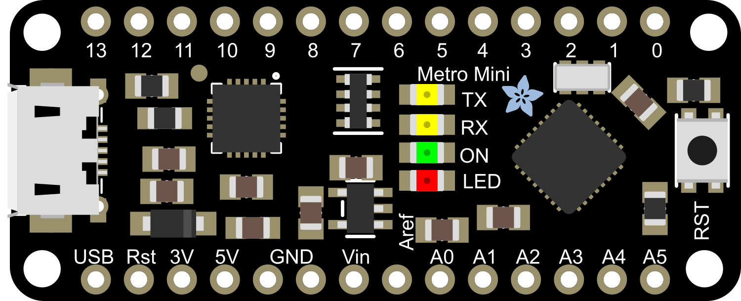
Pin Configuration and Descriptions

Pin Number Function Description
1 RESET Used to reset the microcontroller
2-7 Digital I/O Digital pins, PWM available on pins 3, 5, 6
8-13 Digital I/O Digital pins, PWM available on pins 9, 10, 11
A0-A5 Analog Input Analog input pins
A4, A5 I2C SDA and SCL for I2C communication
A6, A7 Analog Input Additional analog input pins (not on headers)
14 (TX) Serial TX Transmit pin for serial communication
15 (RX) Serial RX Receive pin for serial communication
VIN Voltage Input Input voltage to the board
5V Regulated 5V Output to supply 5V to the circuit
3V3 Regulated 3.3V Output to supply 3.3V to the circuit
GND Ground Common ground for the circuit

Usage Instructions

Integrating with a Circuit

To use the Adafruit Metro Mini in a circuit:

  1. Connect the board to a power source via the VIN pin (6-12V recommended).
  2. Connect the GND pin to the common ground of your circuit.
  3. Utilize the digital and analog pins as required for your project, ensuring you do not exceed the current ratings.
  4. If using PWM, connect to pins 3, 5, 6, 9, 10, or 11.
  5. For I2C communication, use pins A4 (SDA) and A5 (SCL).

Best Practices

  • Always disconnect the Metro Mini from the power source before making or altering connections.
  • Use a current limiting resistor when connecting LEDs to the output pins.
  • Avoid applying voltages higher than 5V to any I/O pin.
  • Ensure that the total current through all I/O pins does not exceed the limit.

Troubleshooting and FAQs

Common Issues

  • Metro Mini not recognized by computer: Ensure the drivers are installed and the USB cable is functioning.
  • Sketch not uploading: Check the board and port settings in the Arduino IDE, and ensure the correct bootloader is selected.
  • I/O pin not working: Verify that the pin is not being overdriven beyond its current limit and that it is configured correctly in your sketch.

Solutions and Tips

  • If the Metro Mini is not recognized, try using a different USB cable or port.
  • When uploading sketches, ensure no other programs are using the same COM port.
  • Use external power supplies for components that draw more current than the Metro Mini can provide.

Example Code for Arduino UNO

Here is a simple example of blinking the onboard LED using the Arduino IDE:

// Pin 13 has an LED connected on most Arduino boards.
int led = 13;

// The setup routine runs once when you press reset:
void setup() {
  // Initialize the digital pin as an output.
  pinMode(led, OUTPUT);
}

// The loop routine runs over and over again forever:
void loop() {
  digitalWrite(led, HIGH);   // Turn the LED on (HIGH is the voltage level)
  delay(1000);               // Wait for a second
  digitalWrite(led, LOW);    // Turn the LED off by making the voltage LOW
  delay(1000);               // Wait for a second
}

Remember to select "Adafruit Metro Mini" as the board in the Arduino IDE before uploading the code. If the Metro Mini is not listed, you may need to install the Adafruit board definitions via the Boards Manager.

For more advanced usage and additional examples, refer to the Adafruit Metro Mini guide and the Arduino language reference.