How to Use prototype module 1pc: Examples, Pinouts, and Specs
Introduction
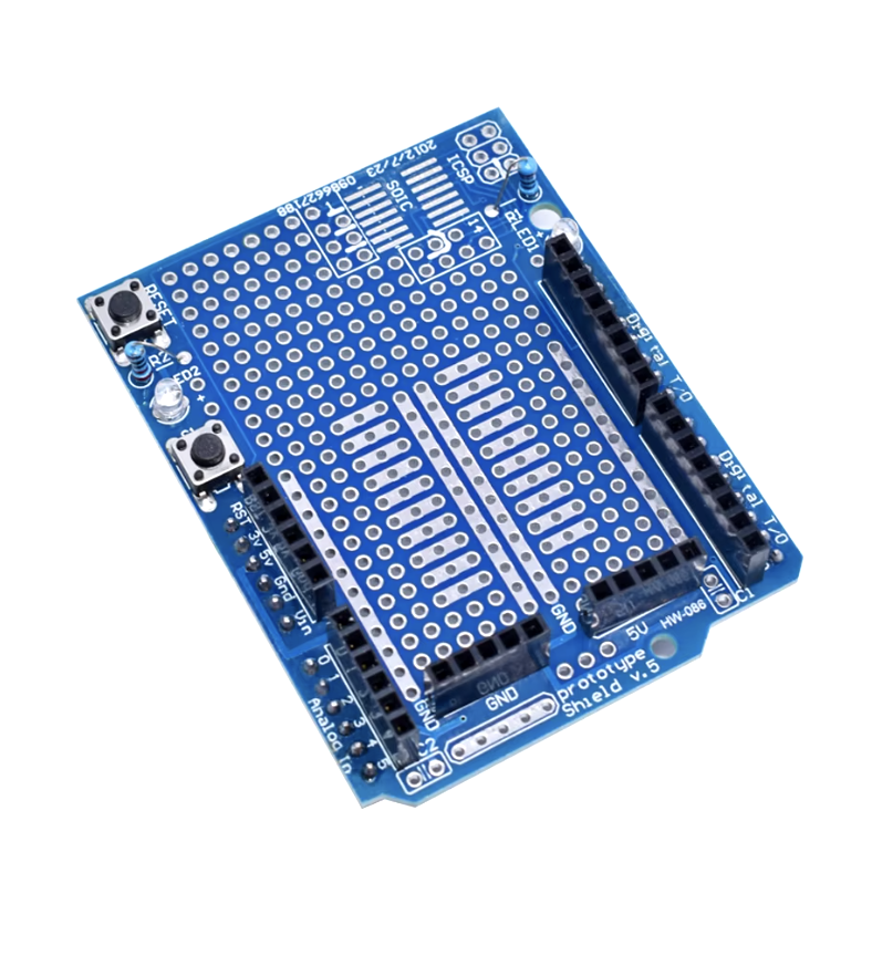
The Elegoo Prototype Module 1pc is a versatile and user-friendly platform designed for hobbyists, engineers, and students to experiment with and test new circuit designs. This module is commonly used in conjunction with Arduino UNO and other microcontroller boards to create prototypes of electronic circuits before finalizing the design for production. It is ideal for quick iterations and learning the basics of electronic circuit design.
Explore Projects Built with prototype module 1pc


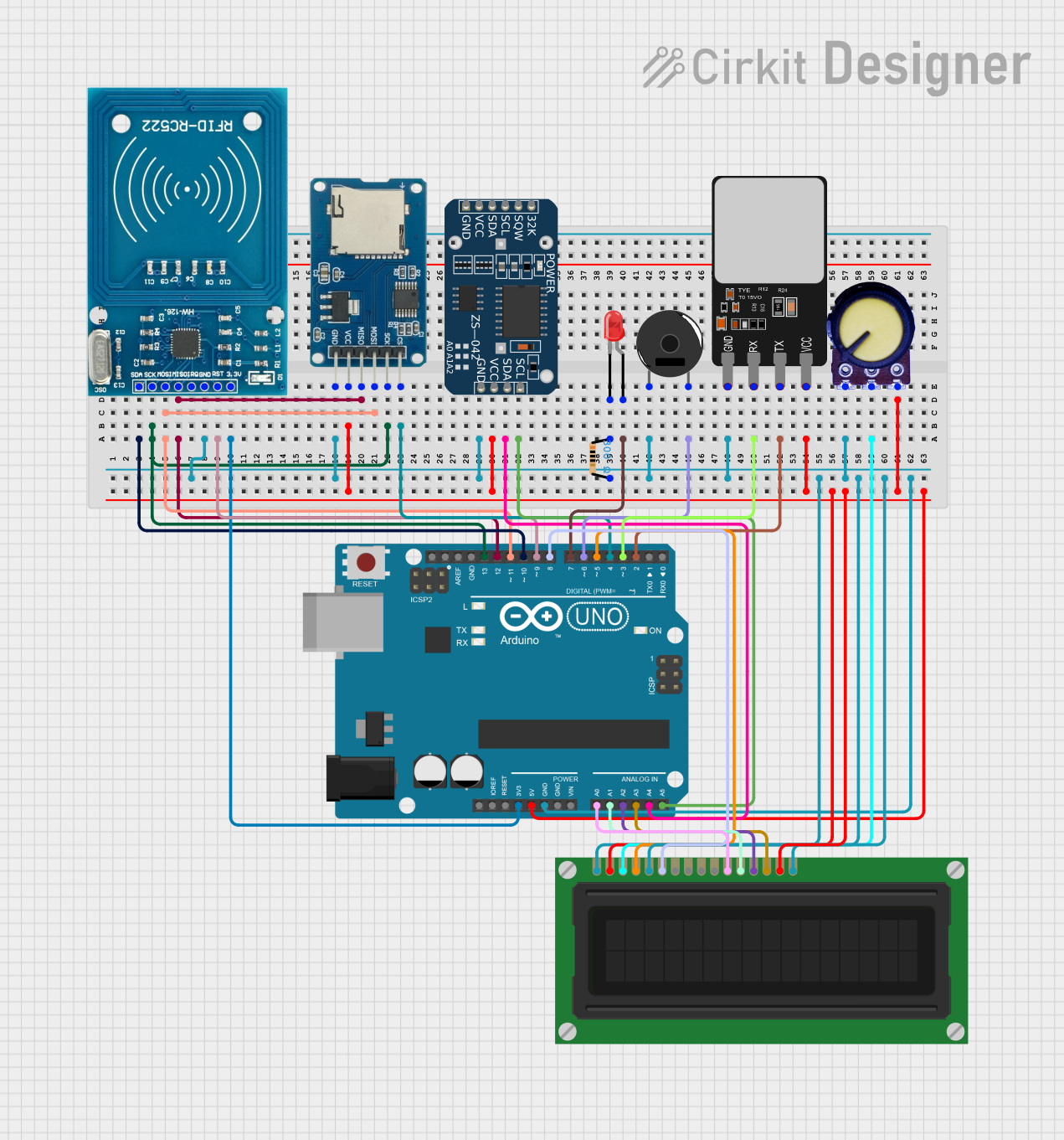
Explore Projects Built with prototype module 1pc
Common Applications and Use Cases
- Rapid prototyping of electronic circuits
- Educational purposes for learning electronics and circuit design
- Testing and debugging circuits before final implementation
- DIY projects and maker initiatives
Technical Specifications
Key Technical Details
- Dimensions: Standard sizing to fit breadboards and development boards
- Material: High-quality PCB with a clear and clean layout
- Compatibility: Designed to be compatible with Arduino UNO and similar microcontroller platforms
Pin Configuration and Descriptions
| Pin Number | Description | Notes |
|---|---|---|
| 1 | VCC | Connect to positive power supply |
| 2 | GND | Connect to ground |
| 3-n | Signal/IO Pins | For interfacing with components |
| n+1 | Additional Features | E.g., LEDs, buttons, etc. |
Note: The actual pin configuration may vary based on the specific design of the prototype module. Please refer to the manufacturer's datasheet for exact details.
Usage Instructions
How to Use the Component in a Circuit
- Power Connections: Connect the VCC and GND pins to your power supply, ensuring that the voltage levels are within the module's specifications.
- Component Placement: Insert electronic components such as resistors, capacitors, and integrated circuits into the provided holes or solder points.
- Wiring: Use jumper wires to create connections between the components and the signal/IO pins as per your circuit design.
- Testing: Once the circuit is assembled, power it up and test its functionality.
Important Considerations and Best Practices
- Voltage and Current: Do not exceed the recommended voltage and current ratings to prevent damage to the module and components.
- Short Circuits: Be cautious of potential short circuits that can occur if components are placed incorrectly.
- Soldering: If soldering components, ensure proper ventilation and use appropriate soldering techniques to avoid cold joints or overheating the PCB.
- Debugging: Use tools like multimeters and oscilloscopes to troubleshoot and verify the correct operation of your circuit.
Troubleshooting and FAQs
Common Issues Users Might Face
- Power Issues: Ensure that the power supply is connected correctly and providing the right voltage.
- Component Failure: Check for any damaged components that may need replacement.
- Poor Connections: Inspect all solder joints and wire connections for continuity and proper contact.
Solutions and Tips for Troubleshooting
- Visual Inspection: Look for any obvious signs of damage or incorrect connections.
- Continuity Testing: Use a multimeter to check for continuity in your circuit paths.
- Isolate Problems: Break down the circuit into smaller sections and test each individually to isolate the issue.
FAQs
Q: Can I reuse the prototype module for multiple projects? A: Yes, the module is designed to be reusable. If you are using a solderless setup, you can easily reconfigure the circuit for new projects.
Q: Is the prototype module compatible with other microcontrollers besides Arduino UNO? A: Generally, yes. The module is designed to be versatile and should work with most microcontroller boards that have similar power and signal requirements.
Q: How do I know if my circuit is working correctly? A: You should verify the functionality of your circuit by testing it with a power supply and using diagnostic tools like a multimeter or an oscilloscope.
Example Arduino UNO Code
// Example code for blinking an LED connected to the prototype module

// Define the pin connected to the LED
const int ledPin = 13; // Use the appropriate pin based on your circuit design

void setup() {
  // Set the LED pin as an output
  pinMode(ledPin, OUTPUT);
}

void loop() {
  digitalWrite(ledPin, HIGH); // Turn the LED on
  delay(1000);                // Wait for a second
  digitalWrite(ledPin, LOW);  // Turn the LED off
  delay(1000);                // Wait for a second
}
Note: The above code is a simple example to demonstrate how to control an LED using an Arduino UNO connected to the prototype module. Modify the pin number and logic according to your specific circuit design.