How to Use ESP32 WIFI MODULE: Examples, Pinouts, and Specs
Introduction
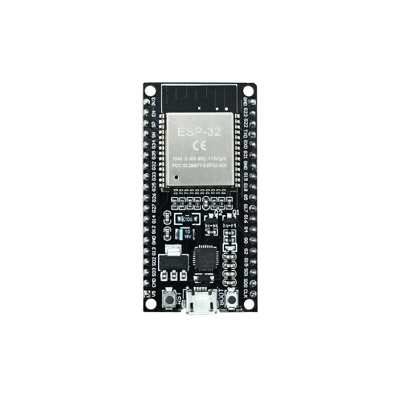
The ESP32 WiFi Module, manufactured by Espressif Systems (Part ID: ESP32), is a powerful and versatile microcontroller designed for Internet of Things (IoT) applications. It integrates both Wi-Fi and Bluetooth capabilities, making it an ideal choice for wireless communication and control in a wide range of projects. The ESP32 is known for its high performance, low power consumption, and extensive peripheral support, making it suitable for applications such as smart home devices, wearables, industrial automation, and more.
Explore Projects Built with ESP32 WIFI MODULE


Explore Projects Built with ESP32 WIFI MODULE
Common Applications and Use Cases
- IoT Devices: Smart home automation, environmental monitoring, and connected appliances.
- Wearables: Fitness trackers, health monitoring devices, and smart watches.
- Industrial Automation: Wireless sensor networks, machine-to-machine communication.
- Robotics: Remote control and telemetry for robots and drones.
- Prototyping: Rapid development of wireless-enabled projects.
Technical Specifications
Key Technical Details
| Parameter | Value |
|---|---|
| Manufacturer | Espressif Systems |
| Part ID | ESP32 |
| Microcontroller Core | Dual-core Xtensa® 32-bit LX6 |
| Clock Speed | Up to 240 MHz |
| Flash Memory | 4 MB (varies by model) |
| SRAM | 520 KB |
| Wireless Connectivity | Wi-Fi 802.11 b/g/n, Bluetooth v4.2 + BLE |
| Operating Voltage | 3.0V to 3.6V |
| GPIO Pins | Up to 34 GPIOs (multiplexed with other functions) |
| ADC Channels | 18 (12-bit resolution) |
| DAC Channels | 2 (8-bit resolution) |
| Communication Interfaces | UART, SPI, I2C, I2S, CAN, PWM, SDIO |
| Power Consumption (Wi-Fi) | Active: ~160 mA, Deep Sleep: ~10 µA |
| Operating Temperature Range | -40°C to +85°C |
| Dimensions | 25.5 mm x 18 mm (varies by module type) |
Pin Configuration and Descriptions
The ESP32 module has multiple pins, each with specific functions. Below is a general pinout for the ESP32:
| Pin Name | Function |
|---|---|
| GPIO0 | General-purpose I/O, boot mode selection |
| GPIO1 (TXD0) | UART0 Transmit (default) |
| GPIO3 (RXD0) | UART0 Receive (default) |
| GPIO12 | General-purpose I/O, ADC2 channel |
| GPIO13 | General-purpose I/O, ADC2 channel, Touch Sensor |
| GPIO14 | General-purpose I/O, ADC2 channel, PWM |
| GPIO15 | General-purpose I/O, ADC2 channel, Touch Sensor |
| GPIO16 | General-purpose I/O, Wake-up from deep sleep |
| GPIO17 | General-purpose I/O |
| EN | Enable pin (active high, resets the module when pulled low) |
| 3V3 | 3.3V power input |
| GND | Ground |
Note: The exact pinout may vary depending on the specific ESP32 module variant (e.g., ESP32-WROOM-32, ESP32-WROVER).
Usage Instructions
How to Use the ESP32 in a Circuit
Powering the Module:
- Provide a stable 3.3V power supply to the
3V3pin. Avoid exceeding 3.6V to prevent damage. - Connect the
GNDpin to the ground of your circuit.
- Provide a stable 3.3V power supply to the
Programming the ESP32:
- Use a USB-to-Serial adapter or a development board (e.g., ESP32 DevKit) to program the module.
- Connect the
TXD0andRXD0pins to the serial adapter for communication. - Install the ESP32 board package in the Arduino IDE or use the Espressif IDF (IoT Development Framework) for advanced programming.
Connecting Peripherals:
- Use the GPIO pins for interfacing with sensors, actuators, and other devices.
- Configure the pins in your code for input, output, or alternate functions (e.g., ADC, PWM).
Wi-Fi and Bluetooth Setup:
- Use the built-in libraries (e.g.,
WiFi.handBluetoothSerial.hin Arduino IDE) to enable wireless communication.
- Use the built-in libraries (e.g.,
Important Considerations and Best Practices
- Voltage Levels: Ensure all connected peripherals operate at 3.3V logic levels. Use level shifters if interfacing with 5V devices.
- Heat Management: The ESP32 can get warm during operation. Ensure proper ventilation or use a heatsink if necessary.
- Deep Sleep Mode: Use deep sleep mode to minimize power consumption in battery-powered applications.
- Boot Mode: Pull GPIO0 low during power-up to enter bootloader mode for programming.
Example Code for Arduino UNO Integration
Below is an example of using the ESP32 to connect to a Wi-Fi network:
#include <WiFi.h> // Include the Wi-Fi library for ESP32

// Replace with your network credentials
const char* ssid = "Your_SSID";
const char* password = "Your_PASSWORD";

void setup() {
  Serial.begin(115200); // Initialize serial communication at 115200 baud
  delay(1000); // Wait for a second to stabilize

  Serial.println("Connecting to Wi-Fi...");
  WiFi.begin(ssid, password); // Start Wi-Fi connection

  // Wait until the ESP32 connects to the Wi-Fi network
  while (WiFi.status() != WL_CONNECTED) {
    delay(500);
    Serial.print(".");
  }

  Serial.println("\nConnected to Wi-Fi!");
  Serial.print("IP Address: ");
  Serial.println(WiFi.localIP()); // Print the assigned IP address
}

void loop() {
  // Add your main code here
}
Troubleshooting and FAQs
Common Issues and Solutions
ESP32 Not Connecting to Wi-Fi:
- Solution: Double-check the SSID and password. Ensure the Wi-Fi network is operational and within range.
- Tip: Use
WiFi.status()to debug connection issues.
Module Not Responding:
- Solution: Verify the power supply voltage and current. Ensure the
ENpin is pulled high. - Tip: Check the serial monitor for error messages during boot.
- Solution: Verify the power supply voltage and current. Ensure the
GPIO Pins Not Working as Expected:
- Solution: Ensure the pins are not being used for other functions (e.g., ADC, UART).
- Tip: Refer to the ESP32 datasheet for pin multiplexing details.
Overheating:
- Solution: Reduce the clock speed or optimize the code to minimize processing load.
- Tip: Use a heatsink or improve ventilation around the module.
FAQs
Q: Can the ESP32 operate on 5V?
- A: No, the ESP32 operates on 3.3V. Use a voltage regulator or level shifter for 5V systems.
Q: How do I reset the ESP32?
- A: Pull the
ENpin low momentarily or press the reset button on a development board.
- A: Pull the
Q: Can I use the ESP32 with the Arduino IDE?
- A: Yes, the ESP32 is fully compatible with the Arduino IDE. Install the ESP32 board package to get started.
Q: What is the maximum range of the ESP32's Wi-Fi?
- A: The range depends on environmental factors but typically extends up to 100 meters in open spaces.
This documentation provides a comprehensive guide to understanding and using the ESP32 WiFi Module. For further details, refer to the official Espressif Systems datasheet and user manual.