
How to Use DC to AC Inverter: Examples, Pinouts, and Specs
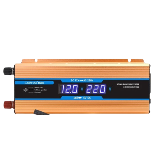
 Design with DC to AC Inverter in Cirkit Designer
Introduction
A DC to AC inverter is an electronic device that converts direct current (DC) into alternating current (AC). This conversion allows DC power sources, such as batteries or solar panels, to power AC devices like household appliances, tools, and lighting systems. Inverters are essential in renewable energy systems, uninterruptible power supplies (UPS), and portable power solutions.
Explore Projects Built with DC to AC Inverter
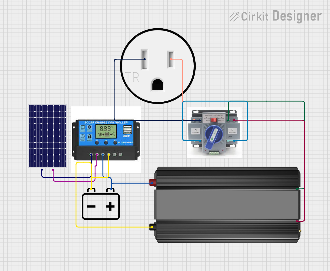 Open Project in Cirkit Designer
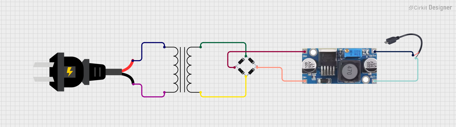 Open Project in Cirkit Designer
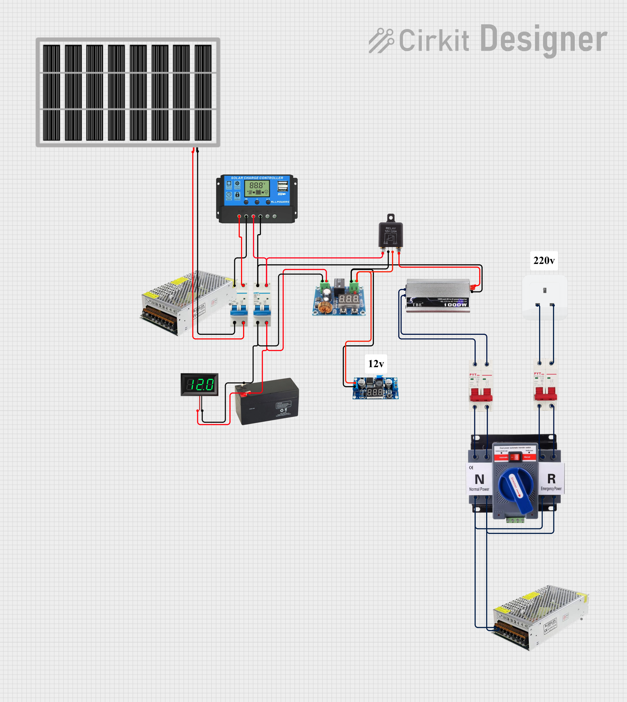 Open Project in Cirkit Designer
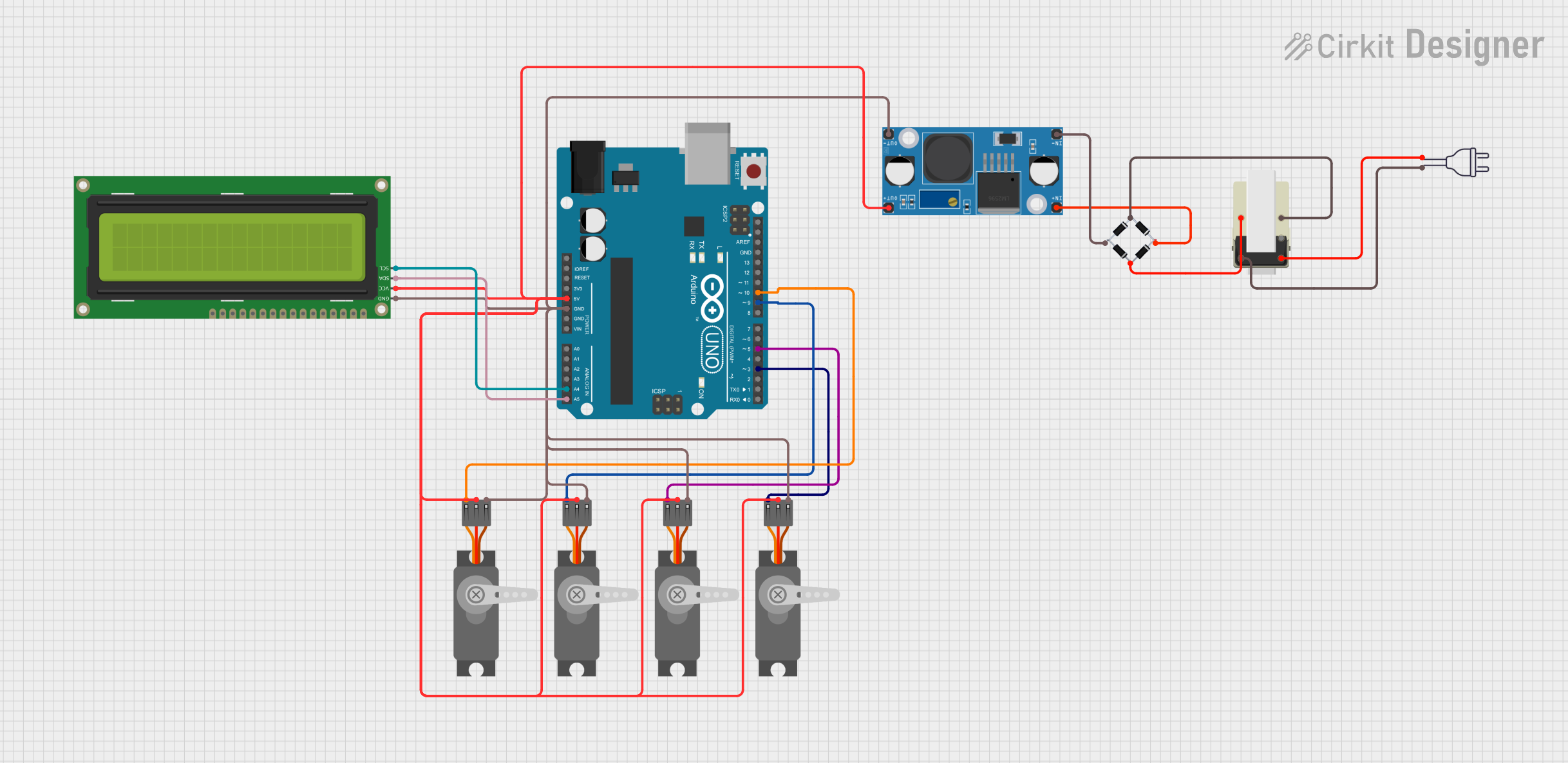 Open Project in Cirkit Designer
Explore Projects Built with DC to AC Inverter
Open Project in Cirkit DesignerOpen Project in Cirkit DesignerOpen Project in Cirkit DesignerOpen Project in Cirkit DesignerCommon Applications and Use Cases
- Renewable Energy Systems: Converts DC from solar panels or wind turbines into AC for home or grid use.
- Uninterruptible Power Supplies (UPS): Provides backup AC power during outages.
- Portable Power Solutions: Powers AC devices using batteries in off-grid or mobile scenarios.
- Electric Vehicles (EVs): Supplies AC power for onboard systems or external devices.
- Industrial Applications: Drives AC motors and equipment from DC sources.
Technical Specifications
Below are the general technical specifications for a typical DC to AC inverter. Note that specific models may vary, so always refer to the manufacturer's datasheet for precise details.
Key Technical Details
- Input Voltage: 12V DC, 24V DC, or 48V DC (depending on the model)
- Output Voltage: 110V AC or 220V AC (region-specific)
- Output Frequency: 50Hz or 60Hz (region-specific)
- Output Waveform: Pure sine wave, modified sine wave, or square wave
- Power Rating: Ranges from 100W to several kilowatts
- Efficiency: Typically 85% to 95%
- Protection Features: Overload, short circuit, over-temperature, and low battery protection
Pin Configuration and Descriptions
The pin configuration for a DC to AC inverter typically includes input and output terminals, as well as control or monitoring interfaces. Below is a general description:
| Pin/Terminal | Description |
|---|---|
| DC Input (+) | Positive terminal for connecting the DC power source (e.g., battery). |
| DC Input (-) | Negative terminal for connecting the DC power source (e.g., battery). |
| AC Output (L) | Live terminal for the AC output. |
| AC Output (N) | Neutral terminal for the AC output. |
| Ground (GND) | Ground terminal for safety and proper operation. |
| Remote Control | Optional terminal for connecting a remote on/off switch (if supported). |
| Status Indicator | LED or digital display for monitoring inverter status (e.g., power, fault). |
Usage Instructions
How to Use the Component in a Circuit
Connect the DC Input:
- Ensure the DC power source matches the inverter's input voltage rating (e.g., 12V, 24V).
- Connect the positive terminal of the DC source to the inverter's DC Input (+) terminal.
- Connect the negative terminal of the DC source to the inverter's DC Input (-) terminal.
Connect the AC Output:
- Connect the AC Output (L) and (N) terminals to the load (e.g., an appliance or device).
- Ensure the load's power rating does not exceed the inverter's maximum output power.
Grounding:
- Connect the Ground (GND) terminal to an appropriate earth ground for safety.
Power On:
- Turn on the inverter using its power switch or remote control (if available).
- Verify that the status indicator shows normal operation.
Important Considerations and Best Practices
- Match Voltage Ratings: Always ensure the DC input voltage matches the inverter's specifications.
- Avoid Overloading: Do not connect loads that exceed the inverter's power rating.
- Use Proper Wiring: Use appropriately rated cables for both DC input and AC output connections.
- Ventilation: Place the inverter in a well-ventilated area to prevent overheating.
- Battery Protection: Use a fuse or circuit breaker between the battery and inverter to protect against overcurrent.
- Waveform Compatibility: Ensure the load is compatible with the inverter's output waveform (pure sine wave is ideal for sensitive electronics).
Arduino UNO Example (Monitoring Inverter Status)
If your inverter has a status output (e.g., a fault signal), you can monitor it using an Arduino UNO. Below is an example code snippet:
// Define the pin connected to the inverter's status output
const int inverterStatusPin = 2; // Digital pin 2

void setup() {
  pinMode(inverterStatusPin, INPUT); // Set the pin as input
  Serial.begin(9600); // Initialize serial communication
}

void loop() {
  int status = digitalRead(inverterStatusPin); // Read the inverter status

  if (status == HIGH) {
    // If the status pin is HIGH, the inverter is operating normally
    Serial.println("Inverter Status: Normal");
  } else {
    // If the status pin is LOW, there may be a fault
    Serial.println("Inverter Status: Fault Detected");
  }

  delay(1000); // Wait for 1 second before checking again
}
Troubleshooting and FAQs
Common Issues Users Might Face
Inverter Does Not Turn On:
- Cause: Insufficient DC input voltage or loose connections.
- Solution: Check the DC power source and ensure proper connections.
Overload or Shutdown:
- Cause: Load exceeds the inverter's power rating.
- Solution: Reduce the load to within the inverter's capacity.
Overheating:
- Cause: Poor ventilation or excessive load.
- Solution: Ensure adequate airflow around the inverter and reduce the load.
No AC Output:
- Cause: Faulty wiring or internal fault.
- Solution: Verify AC output connections and check the status indicator for faults.
Noise or Interference:
- Cause: Modified sine wave output causing issues with sensitive devices.
- Solution: Use a pure sine wave inverter for sensitive electronics.
Solutions and Tips for Troubleshooting
- Check Connections: Ensure all terminals are securely connected and free of corrosion.
- Monitor Input Voltage: Use a multimeter to verify the DC input voltage is within the specified range.
- Inspect the Load: Disconnect all loads and test the inverter with a smaller, known-good load.
- Refer to the Manual: Consult the manufacturer's manual for model-specific troubleshooting steps.
By following this documentation, users can effectively utilize a DC to AC inverter for various applications while ensuring safe and reliable operation.