
How to Use Arduino Pro Mini v13 (A4/A5 headers): Examples, Pinouts, and Specs
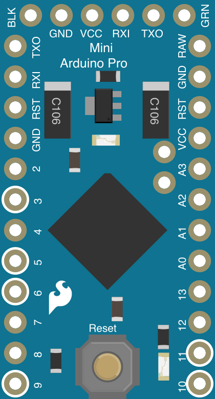
 Design with Arduino Pro Mini v13 (A4/A5 headers) in Cirkit Designer
Introduction
The Arduino Pro Mini v13 is a compact microcontroller board developed by SparkFun, based on the ATmega328P microcontroller. Designed for embedded and space-constrained projects, it offers a minimalist design without onboard USB, requiring an external FTDI or USB-to-serial adapter for programming. This version includes dedicated A4 and A5 headers, making it ideal for I2C communication with sensors and modules.
Explore Projects Built with Arduino Pro Mini v13 (A4/A5 headers)
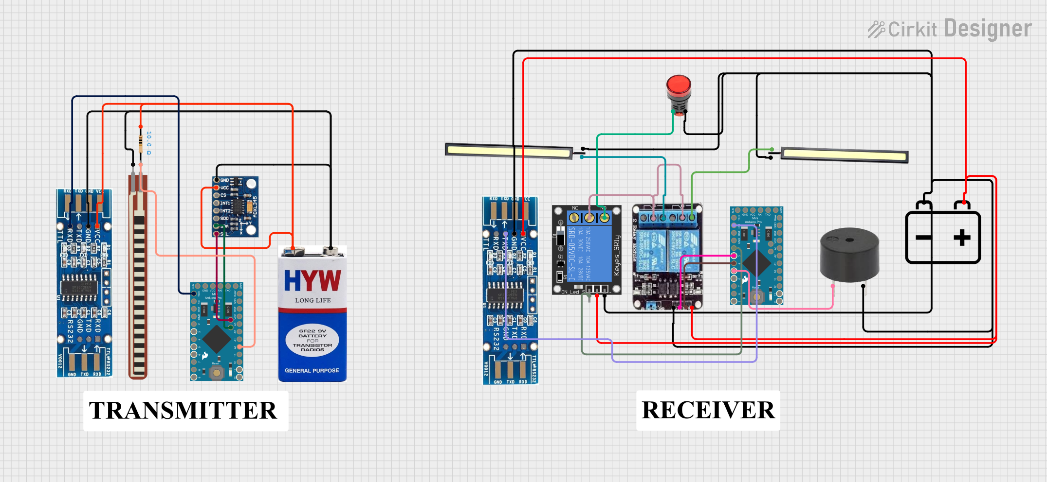 Open Project in Cirkit Designer
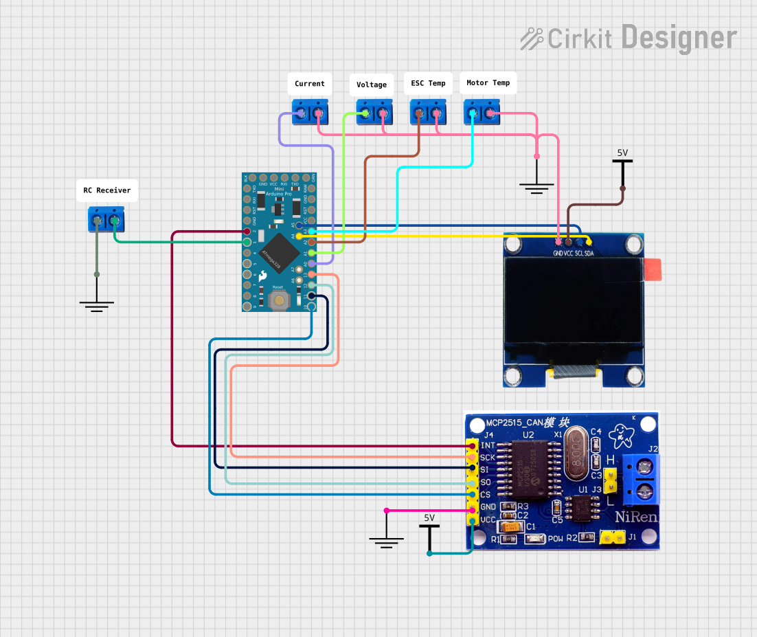 Open Project in Cirkit Designer
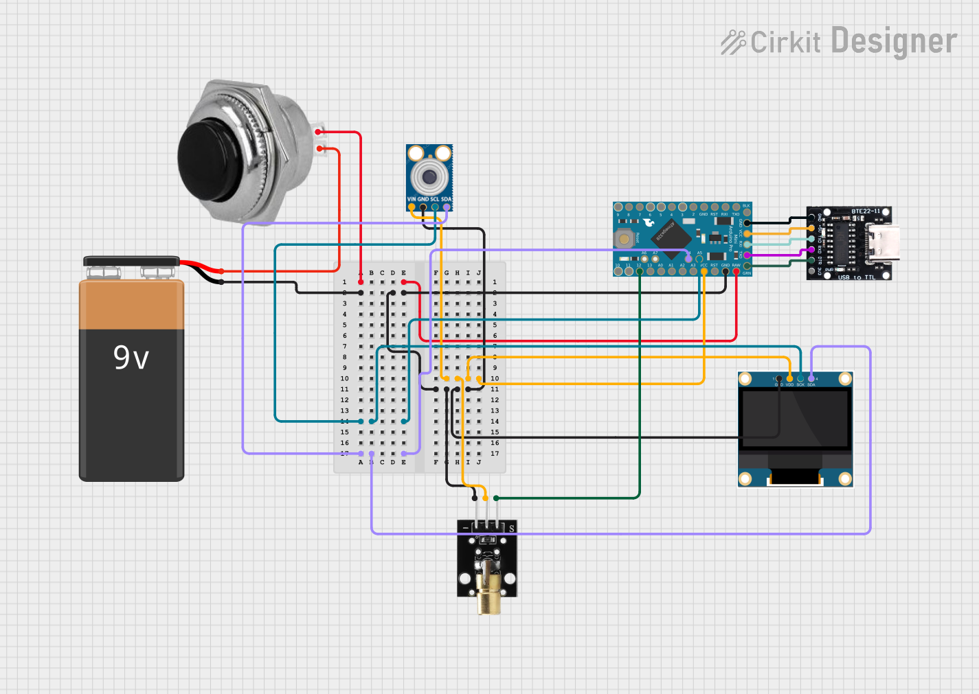 Open Project in Cirkit Designer
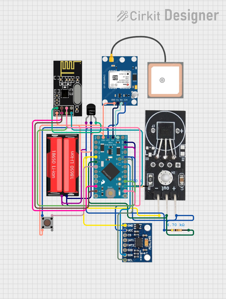 Open Project in Cirkit Designer
Explore Projects Built with Arduino Pro Mini v13 (A4/A5 headers)
Open Project in Cirkit DesignerOpen Project in Cirkit DesignerOpen Project in Cirkit DesignerOpen Project in Cirkit DesignerCommon Applications
- IoT (Internet of Things) devices
- Wearable electronics
- Robotics and automation
- Sensor data acquisition
- Prototyping and small-scale production
Technical Specifications
Below are the key technical details of the Arduino Pro Mini v13:
| Specification | Details |
|---|---|
| Microcontroller | ATmega328P |
| Operating Voltage | 3.3V or 5V (depending on version) |
| Input Voltage (RAW pin) | 3.3V version: 3.4V–12V |
| 5V version: 5V–12V | |
| Digital I/O Pins | 14 (6 PWM outputs) |
| Analog Input Pins | 8 |
| Clock Speed | 8 MHz (3.3V version) or 16 MHz (5V version) |
| Flash Memory | 32 KB (0.5 KB used by bootloader) |
| SRAM | 2 KB |
| EEPROM | 1 KB |
| Communication Protocols | UART, SPI, I2C |
| Dimensions | 18 mm x 33 mm |
Pin Configuration and Descriptions
The Arduino Pro Mini v13 features a total of 24 pins, including power, digital I/O, and analog input pins. Below is the pin configuration:
Power Pins
| Pin | Description |
|---|---|
| RAW | Input for unregulated voltage (3.4V–12V for 3.3V version, 5V–12V for 5V version) |
| VCC | Regulated output voltage (3.3V or 5V, depending on the board version) |
| GND | Ground connection |
Digital I/O Pins
| Pin | Description |
|---|---|
| D0-D13 | General-purpose digital I/O pins. Pins D3, D5, D6, D9, D10, and D11 support PWM. |
Analog Input Pins
| Pin | Description |
|---|---|
| A0-A7 | Analog input pins. Can also be used as digital I/O pins. |
Special Pins
| Pin | Description |
|---|---|
| A4 | Dedicated SDA pin for I2C communication |
| A5 | Dedicated SCL pin for I2C communication |
| RST | Reset pin. Pull low to reset the microcontroller. |
Usage Instructions
How to Use the Arduino Pro Mini v13 in a Circuit
Powering the Board:
- Use the RAW pin for unregulated voltage input (e.g., from a battery or power adapter).
- Alternatively, supply regulated voltage directly to the VCC pin.
Programming the Board:
- Connect an FTDI adapter or USB-to-serial converter to the 6-pin header.
- Ensure the FTDI adapter's voltage matches the board's operating voltage (3.3V or 5V).
- Use the Arduino IDE to upload sketches. Select Arduino Pro or Pro Mini as the board and the appropriate processor (ATmega328P at 3.3V/8MHz or 5V/16MHz).
Connecting I2C Devices:
- Use the A4 (SDA) and A5 (SCL) headers for I2C communication.
- Pull-up resistors (typically 4.7kΩ) may be required on the SDA and SCL lines.
Using Digital and Analog Pins:
- Configure digital pins as input or output using the
pinMode()function. - Read analog values from A0-A7 using the
analogRead()function.
- Configure digital pins as input or output using the
Example: Connecting an I2C Sensor (e.g., MPU6050 Accelerometer)
Below is an example of how to connect and program the Arduino Pro Mini v13 to read data from an MPU6050 sensor:
Wiring Diagram
| Arduino Pro Mini Pin | MPU6050 Pin |
|---|---|
| A4 (SDA) | SDA |
| A5 (SCL) | SCL |
| VCC | VCC |
| GND | GND |
Sample Code
#include <Wire.h>
#include <MPU6050.h>

MPU6050 mpu;

void setup() {
  Wire.begin(); // Initialize I2C communication
  Serial.begin(9600); // Start serial communication for debugging

  // Initialize MPU6050
  if (!mpu.begin(MPU6050_SCALE_2000DPS, MPU6050_RANGE_2G)) {
    Serial.println("Could not find a valid MPU6050 sensor!");
    while (1); // Halt execution if sensor initialization fails
  }
  Serial.println("MPU6050 initialized successfully!");
}

void loop() {
  Vector rawAccel = mpu.readRawAccel(); // Read raw accelerometer data

  // Print accelerometer data to the Serial Monitor
  Serial.print("X: ");
  Serial.print(rawAccel.XAxis);
  Serial.print(" | Y: ");
  Serial.print(rawAccel.YAxis);
  Serial.print(" | Z: ");
  Serial.println(rawAccel.ZAxis);

  delay(500); // Wait 500ms before the next reading
}
Important Considerations
- Ensure the operating voltage of connected peripherals matches the board's voltage (3.3V or 5V).
- Use appropriate pull-up resistors for I2C communication if not already included in the sensor/module.
- Avoid exceeding the maximum input voltage on the RAW pin to prevent damage.
Troubleshooting and FAQs
Common Issues and Solutions
1. **Board Not Detected by Arduino IDE**
- Ensure the correct board and processor are selected in the Arduino IDE.
- Verify the FTDI adapter is properly connected and powered.
- Check that the FTDI adapter's voltage matches the board's operating voltage.
2. **Sketch Upload Fails**
- Ensure the correct COM port is selected in the Arduino IDE.
- Press the RESET button on the board just before uploading the sketch.
- Verify the FTDI adapter's drivers are installed correctly.
3. **I2C Devices Not Responding**
- Check the wiring of the SDA and SCL lines.
- Ensure pull-up resistors are present on the I2C lines.
- Use an I2C scanner sketch to detect connected devices.
FAQs
Q: Can I power the Arduino Pro Mini directly from a USB port?
A: No, the Arduino Pro Mini does not have onboard USB. Use an FTDI adapter or USB-to-serial converter for programming and power.
Q: What is the difference between the 3.3V and 5V versions?
A: The 3.3V version operates at 8 MHz and is suitable for low-power applications, while the 5V version operates at 16 MHz and is better for higher-speed applications.
Q: Do I need external pull-up resistors for I2C communication?
A: Yes, if the connected I2C devices do not have built-in pull-up resistors, you need to add them (typically 4.7kΩ).
By following this documentation, you can effectively integrate the Arduino Pro Mini v13 into your projects and troubleshoot common issues.