Cirkit Designer
Your all-in-one circuit design IDE
Home /
Component Documentation
How to Use XL4016: Examples, Pinouts, and Specs
Introduction
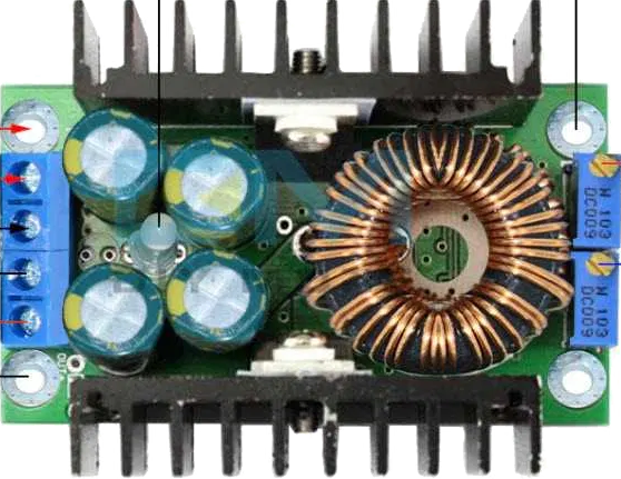
The XL4016 is a high-efficiency, step-down DC/DC converter capable of delivering up to 8A of output current. It is designed to efficiently reduce higher voltages to a lower voltage, making it ideal for applications requiring a high-power buck converter. Common applications include battery chargers, power supplies, and LED drivers.
Explore Projects Built with XL4016
ESP32-Powered Wi-Fi Controlled Robotic Car with OLED Display and Ultrasonic Sensor

This circuit is a battery-powered system featuring an ESP32 microcontroller that controls an OLED display, a motor driver for two hobby motors, an ultrasonic sensor for distance measurement, and a DFPlayer Mini for audio output through a loudspeaker. The TP4056 module manages battery charging, and a step-up boost converter provides a stable 5V supply to the components.
Lilygo 7670e-Based Smart Interface with LCD Display and Keypad

This circuit features a Lilygo 7670e microcontroller interfaced with a 16x2 I2C LCD for display, a 4X4 membrane matrix keypad for input, and an arcade button for additional control. It also includes a 4G antenna and a GPS antenna for communication and location tracking capabilities.
ESP8266 NodeMCU Wi-Fi Enabled OLED Display with RYLR896 Communication Module

This circuit features an ESP8266 NodeMCU microcontroller connected to a 0.96" OLED display and an RYLR896 LoRa module. The ESP8266 communicates with the OLED via I2C protocol and interfaces with the LoRa module using UART, enabling wireless data transmission and display capabilities.
ESP32-Based Battery-Powered Multi-Sensor System

This circuit consists of a TP4056 module connected to a 3.7V LiPo battery, providing a charging interface for the battery. The TP4056 manages the charging process by connecting its B+ and B- pins to the battery's positive and ground terminals, respectively.
Explore Projects Built with XL4016
ESP32-Powered Wi-Fi Controlled Robotic Car with OLED Display and Ultrasonic Sensor
This circuit is a battery-powered system featuring an ESP32 microcontroller that controls an OLED display, a motor driver for two hobby motors, an ultrasonic sensor for distance measurement, and a DFPlayer Mini for audio output through a loudspeaker. The TP4056 module manages battery charging, and a step-up boost converter provides a stable 5V supply to the components.
Lilygo 7670e-Based Smart Interface with LCD Display and Keypad
This circuit features a Lilygo 7670e microcontroller interfaced with a 16x2 I2C LCD for display, a 4X4 membrane matrix keypad for input, and an arcade button for additional control. It also includes a 4G antenna and a GPS antenna for communication and location tracking capabilities.
ESP8266 NodeMCU Wi-Fi Enabled OLED Display with RYLR896 Communication Module
This circuit features an ESP8266 NodeMCU microcontroller connected to a 0.96" OLED display and an RYLR896 LoRa module. The ESP8266 communicates with the OLED via I2C protocol and interfaces with the LoRa module using UART, enabling wireless data transmission and display capabilities.
ESP32-Based Battery-Powered Multi-Sensor System
This circuit consists of a TP4056 module connected to a 3.7V LiPo battery, providing a charging interface for the battery. The TP4056 manages the charging process by connecting its B+ and B- pins to the battery's positive and ground terminals, respectively.
Technical Specifications
Key Features
- Input Voltage Range: 8V to 40V
- Output Voltage Range: 1.25V to 36V (adjustable via potentiometer)
- Output Current: Up to 8A (with proper heat sinking)
- Efficiency: Up to 94%
- Switching Frequency: 180kHz
- Built-in over-temperature and over-current protection
Pin Configuration and Descriptions
| Pin Number | Pin Name | Description |
|---|---|---|
| 1 | VIN | Input voltage (8V to 40V) |
| 2 | GND | Ground |
| 3 | VOUT | Output voltage (1.25V to 36V) |
| 4 | ADJ | Adjust output voltage (via external resistor) |
| 5 | EN | Enable pin (active high) |
Usage Instructions
Connecting the XL4016 to a Circuit
- Connect the input voltage source to the VIN and GND pins, ensuring that the voltage is within the specified range.
- Connect the load to the VOUT and GND pins.
- Adjust the output voltage by turning the onboard potentiometer or by connecting a resistor to the ADJ pin.
- Optionally, connect the EN pin to a logic high signal to enable the device. If always on operation is desired, the EN pin can be left unconnected or tied to VIN.
Important Considerations and Best Practices
- Always ensure that the input voltage does not exceed the maximum rating of 40V.
- Use proper heat sinking to manage heat dissipation, especially when operating at high currents.
- Place a capacitor close to the input and output pins to minimize voltage spikes and improve stability.
- Avoid running the regulator at its maximum current rating for extended periods to prevent overheating and potential damage.
Troubleshooting and FAQs
Common Issues
- Output voltage is too high or too low: Check the potentiometer or external resistor connected to the ADJ pin for proper adjustment.
- Regulator is overheating: Ensure adequate heat sinking is in place, and the current draw is within the specified limits.
- No output voltage: Verify that the input voltage is within the specified range and that the EN pin is receiving a high signal if used.
Solutions and Tips
- If the output voltage is unstable, add a larger capacitor to the output to improve stability.
- If the device is not turning on, check the connections to the EN pin and ensure it is either left floating, tied to VIN, or receiving a high logic level.
Example Connection with Arduino UNO
// No direct code is required for the XL4016 as it is a hardware component.
// However, you can use an Arduino to control the EN pin if desired.

const int enablePin = 7; // Connect the EN pin of XL4016 to digital pin 7 on Arduino

void setup() {
  pinMode(enablePin, OUTPUT);
  digitalWrite(enablePin, HIGH); // Enable the XL4016
}

void loop() {
  // Your code here to control the XL4016 enable pin
  // For example, to toggle the regulator on and off:
  digitalWrite(enablePin, HIGH); // Turn on XL4016
  delay(5000);                  // Wait for 5 seconds
  digitalWrite(enablePin, LOW);  // Turn off XL4016
  delay(5000);                  // Wait for 5 seconds
}
Remember to ensure that the Arduino's output pin can handle the logic level required by the XL4016's EN pin. If you need to control the output voltage dynamically, you would need additional circuitry, such as a digital potentiometer or a DAC, interfaced with the Arduino to adjust the ADJ pin.