How to Use LM358: Examples, Pinouts, and Specs

Introduction
The LM358 is a versatile dual operational amplifier (op-amp) integrated circuit (IC) that is commonly used in a variety of electronic applications. It is designed for standard operational amplifier applications and is particularly well-suited for single-supply operations. The LM358 is widely used in audio amplification, voltage and current sensing, signal conditioning circuits, and other applications that require low input bias current, low input offset voltage, and a wide bandwidth.
Explore Projects Built with LM358
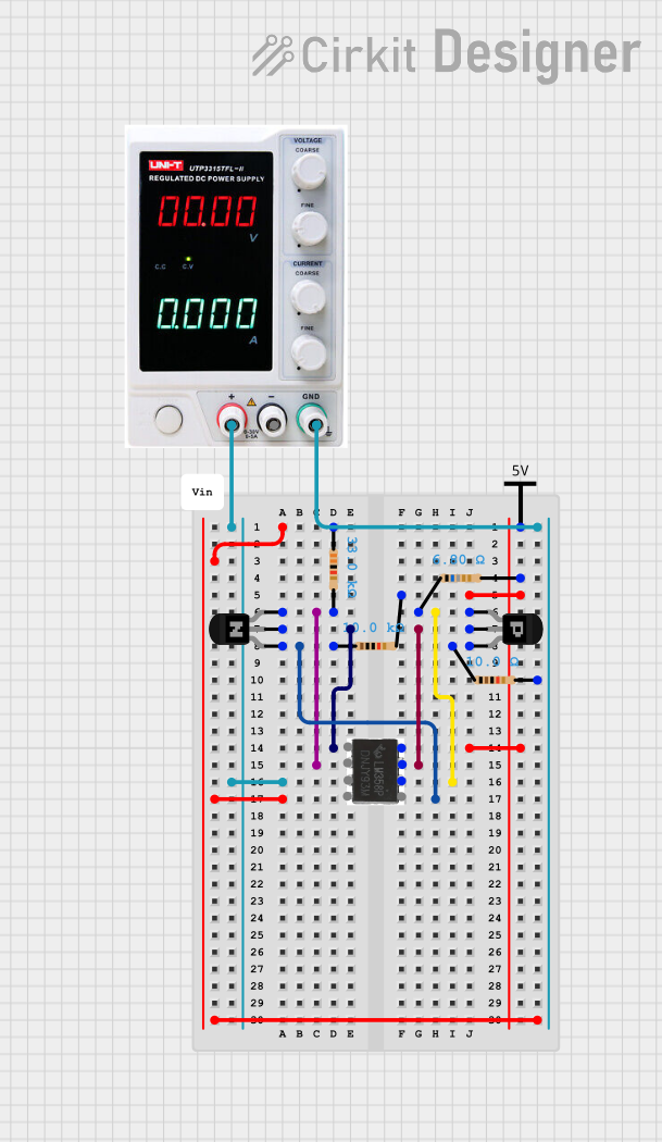


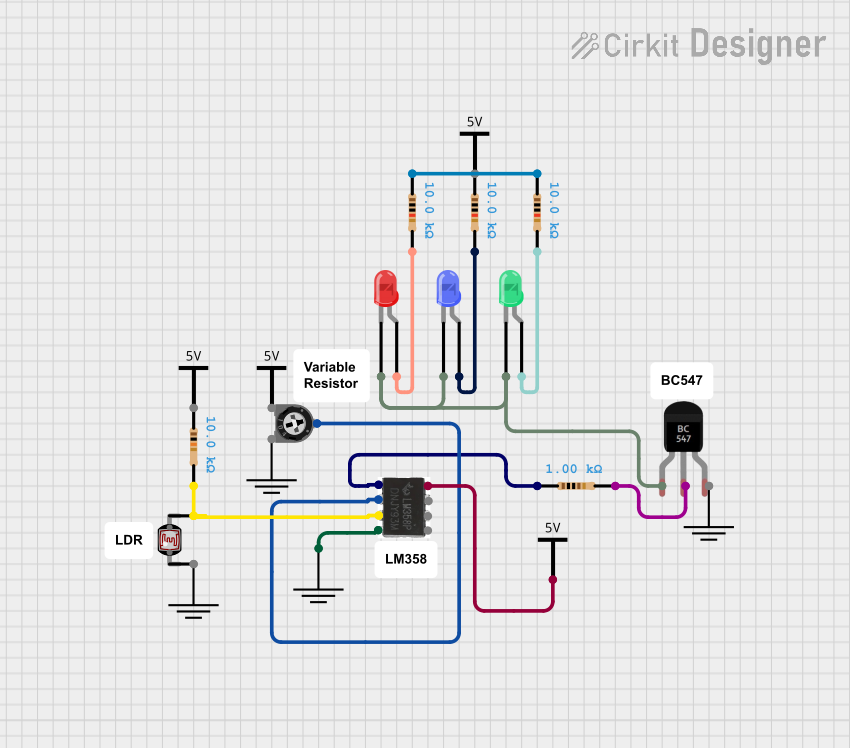
Explore Projects Built with LM358
Technical Specifications
Key Technical Details
- Supply Voltage (VCC): 3V to 32V
- Input Offset Voltage: Typically 2mV
- Input Bias Current: Typically 20nA
- Operating Temperature Range: 0°C to 70°C
- Bandwidth: 0.7MHz
- Slew Rate: 0.3 V/µs
- Output Short-Circuit Current: Typically 20mA
- Package Types: DIP-8, SOIC-8
Pin Configuration and Descriptions
| Pin Number | Pin Name | Description |
|---|---|---|
| 1 | OUT A | Output of Amplifier A |
| 2 | IN A(-) | Inverting Input of Amplifier A |
| 3 | IN A(+) | Non-Inverting Input of Amplifier A |
| 4 | VEE | Ground or Negative Supply Voltage |
| 5 | IN B(+) | Non-Inverting Input of Amplifier B |
| 6 | IN B(-) | Inverting Input of Amplifier B |
| 7 | OUT B | Output of Amplifier B |
| 8 | VCC | Positive Supply Voltage |
Usage Instructions
How to Use the LM358 in a Circuit
- Power Supply: Connect the positive supply voltage to pin 8 (VCC) and the negative supply or ground to pin 4 (VEE).
- Signal Inputs: Connect the signal you wish to amplify to the non-inverting input (IN A(+) or IN B(+)) of the desired amplifier. If you need to invert the signal, connect it to the inverting input (IN A(-) or IN B(-)).
- Feedback Loop: To set the gain of the amplifier, connect a feedback resistor between the output (OUT A or OUT B) and the inverting input (IN A(-) or IN B(-)). You may also need a resistor between the non-inverting input and ground to set the input impedance.
- Output: The amplified signal can be taken from the output pins (OUT A or OUT B).
Important Considerations and Best Practices
- Bypass Capacitors: Place a 0.1µF ceramic capacitor close to the power supply pins to filter out noise.
- Gain Bandwidth Product: Remember that the gain and bandwidth are inversely related. Higher gain settings will result in lower bandwidth.
- Input Bias Current: The input bias current is low, but it can still affect high-impedance signal sources. Use appropriate biasing techniques to minimize errors.
- Single Supply Operation: When using a single supply, ensure that the input signal is biased at half the supply voltage to maximize the output swing.
Example Circuit: Non-Inverting Amplifier with Arduino UNO
// Define the analog input and output pins
const int analogInPin = A0; // Analog input pin connected to the op-amp output
const int analogOutPin = 9; // PWM output pin

int sensorValue = 0;        // Value read from the op-amp
int outputValue = 0;        // Value output to the PWM (analog out)

void setup() {
  // Initialize serial communications at 9600 bps:
  Serial.begin(9600);
}

void loop() {
  // Read the analog value from the op-amp output
  sensorValue = analogRead(analogInPin);
  // Map it to the range of the analog out (PWM):
  outputValue = map(sensorValue, 0, 1023, 0, 255);
  // Change the analog out value:
  analogWrite(analogOutPin, outputValue);

  // Print the results to the serial monitor:
  Serial.print("sensor = ");
  Serial.print(sensorValue);
  Serial.print("\t output = ");
  Serial.println(outputValue);

  // Wait 2 milliseconds before the next loop
  // for the analog-to-digital converter to settle
  // after the last reading:
  delay(2);
}
Troubleshooting and FAQs
Common Issues
- Output Not as Expected: Ensure that the power supply is within the specified range and that the input signal is properly biased.
- Low Output Swing: This can occur if the op-amp is not properly biased in single-supply operations. Make sure the input signal is centered around VCC/2.
- Noise in the Output: Check for proper decoupling and that the bypass capacitors are in place. Also, ensure that the feedback resistors are of appropriate values.
Solutions and Tips for Troubleshooting
- Check Supply Voltages: Verify that the supply voltages are within the specified range and are stable.
- Inspect Pin Connections: Ensure that all pins are correctly connected according to the pin configuration.
- Signal Integrity: Use an oscilloscope to check the integrity of the input and output signals.
FAQs
Q: Can the LM358 be used with a single power supply? A: Yes, the LM358 is designed to work well with a single power supply.
Q: What is the maximum supply voltage for the LM358? A: The maximum supply voltage is 32V.
Q: Can I use the LM358 for high-frequency applications? A: The LM358 has a bandwidth of 0.7MHz, which may not be suitable for high-frequency applications.
Q: Is the LM358 suitable for driving heavy loads? A: The LM358 can source or sink up to 20mA. For heavier loads, external power stages may be required.