How to Use 2-Channel Relay (5V 10A): Examples, Pinouts, and Specs
Introduction
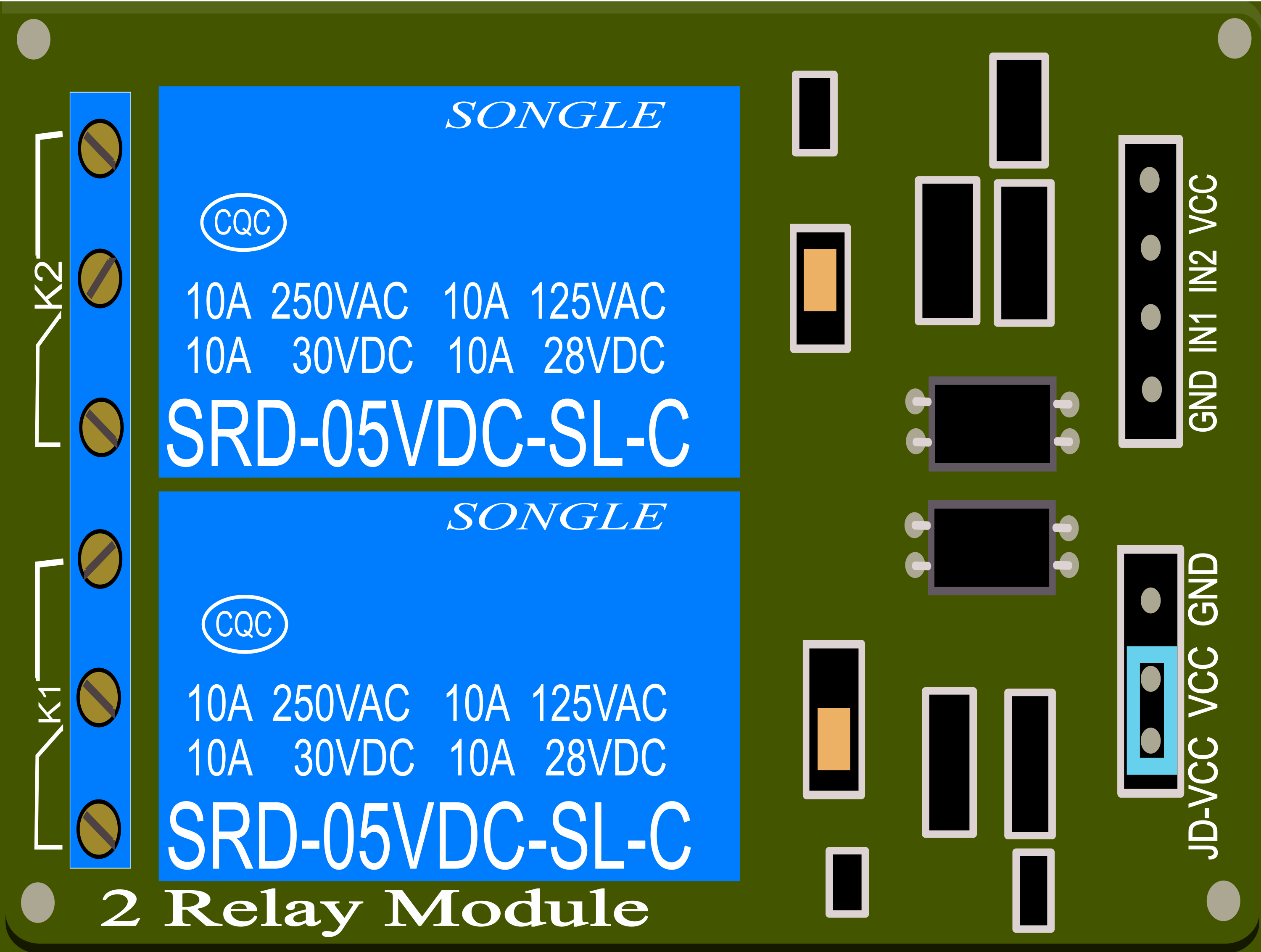
A 2-Channel Relay is an electronic device that functions as an electrically operated switch. It allows a low-power signal to control a much higher power circuit. This particular 2-channel relay operates at 5V and can handle a maximum current of 10A per channel. It is commonly used in applications where it is necessary to control high power devices such as motors, lights, and other appliances with a low-power signal from a microcontroller like an Arduino UNO.
Explore Projects Built with 2-Channel Relay (5V 10A)


Explore Projects Built with 2-Channel Relay (5V 10A)
Common Applications and Use Cases
- Home automation systems
- Remote control switches
- Industrial controls
- Automotive electronics
- Robotics
Technical Specifications
Key Technical Details
- Operating Voltage: 5V DC
- Maximum Current: 10A per channel at 250V AC or 30V DC
- Number of Channels: 2
- Control Signal: TTL level from 0V to 5V
- Contact Type: SPDT (Single Pole Double Throw)
- Switching Time: Typically 5-10ms
Pin Configuration and Descriptions
| Pin Number | Description | Type |
|---|---|---|
| 1 | VCC | Power |
| 2 | GND | Ground |
| 3 | IN1 | Input |
| 4 | IN2 | Input |
| 5 | COM1 (Common) | Output |
| 6 | NO1 (Normally Open) | Output |
| 7 | NC1 (Normally Closed) | Output |
| 8 | COM2 (Common) | Output |
| 9 | NO2 (Normally Open) | Output |
| 10 | NC2 (Normally Closed) | Output |
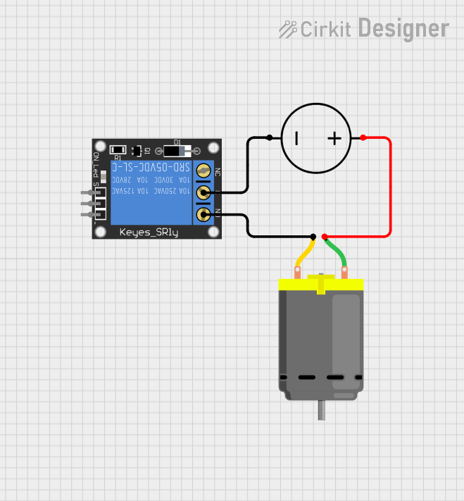
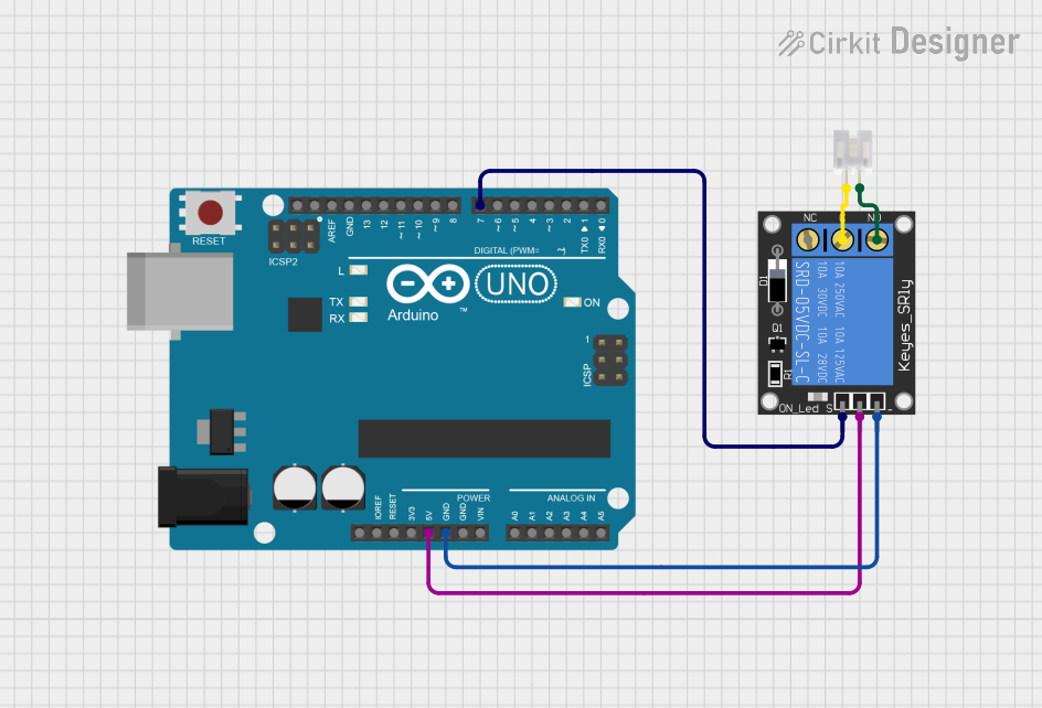
Usage Instructions
How to Use the Component in a Circuit
- Connect the VCC pin to a 5V power supply.
- Connect the GND pin to the ground of the power supply.
- Connect the IN1 and IN2 pins to the digital outputs of a microcontroller.
- Connect the device you wish to control to the COM (Common) and NO (Normally Open) or NC (Normally Closed) pins.
Important Considerations and Best Practices
- Ensure that the power supply does not exceed 5V as it may damage the relay.
- Do not exceed the maximum current rating of 10A per channel.
- Use flyback diodes when controlling inductive loads to prevent back EMF damage.
- Always ensure proper isolation between the low voltage and high voltage sides.
Example Code for Arduino UNO
// Define relay control pins
const int relayPin1 = 2;
const int relayPin2 = 3;

void setup() {
  // Set relay pins as output
  pinMode(relayPin1, OUTPUT);
  pinMode(relayPin2, OUTPUT);

  // Initialize relays to OFF (Normally Open state)
  digitalWrite(relayPin1, LOW);
  digitalWrite(relayPin2, LOW);
}

void loop() {
  // Turn on relay 1
  digitalWrite(relayPin1, HIGH);
  delay(1000); // Wait for 1 second

  // Turn off relay 1
  digitalWrite(relayPin1, LOW);
  delay(1000); // Wait for 1 second

  // Turn on relay 2
  digitalWrite(relayPin2, HIGH);
  delay(1000); // Wait for 1 second

  // Turn off relay 2
  digitalWrite(relayPin2, LOW);
  delay(1000); // Wait for 1 second
}
Troubleshooting and FAQs
Common Issues
- Relay not activating: Check the wiring and ensure the control signal is reaching the relay. Also, verify the power supply is 5V.
- Intermittent operation: Ensure that there is no loose connection and the current does not exceed 10A.
- Noise issues: When controlling inductive loads, ensure a flyback diode is used to suppress voltage spikes.
Solutions and Tips for Troubleshooting
- Double-check all connections, especially the ground between the Arduino and the relay module.
- Use a multimeter to verify the presence of the control voltage at the relay's input.
- If controlling AC loads, ensure proper safety measures and consider consulting a professional electrician.
FAQs
Q: Can I control this relay with a 3.3V signal? A: While the relay operates at 5V, some 5V relays can be triggered with a 3.3V signal. However, it is best to check the datasheet or test the relay with a 3.3V signal to ensure reliable operation.
Q: Is it safe to control mains voltage with this relay? A: Yes, the relay can switch mains voltage, but you must ensure proper safety precautions and isolation. If unsure, seek professional assistance.
Q: Can I use PWM to control the relay? A: Relays are not designed for high-speed switching and using PWM is not recommended. They are intended for on/off control with a sufficient delay between switching.