Cirkit Designer Logo
Cirkit Designer
Your all-in-one circuit design IDE
Home / 
Component Documentation

How to Use motor driver : Examples, Pinouts, and Specs

Image of motor driver
Cirkit Designer LogoDesign with motor driver in Cirkit Designer

Introduction

A motor driver is an essential component in robotics and automation, allowing precise control over the speed and direction of motors. The Cytron 2020 motor driver is a versatile and robust module designed to interface with a wide range of motors, including DC, stepper, and servo motors. Common applications include robotic vehicles, conveyor systems, and positioning mechanisms.

Explore Projects Built with motor driver

Use Cirkit Designer to design, explore, and prototype these projects online. Some projects support real-time simulation. Click "Open Project" to start designing instantly!
ESP32 and L298N Motor Driver Controlled Battery-Powered Robotic Car
Image of ESP 32 BT BOT: A project utilizing motor driver  in a practical application
This circuit is a motor control system powered by a 12V battery, utilizing an L298N motor driver to control four DC gearmotors. An ESP32 microcontroller is used to send control signals to the motor driver, enabling precise control of the motors for applications such as a robotic vehicle.
Cirkit Designer LogoOpen Project in Cirkit Designer
Arduino-Controlled Dual Motor Driver with IR Sensing
Image of Line follower 14 IR Sensor channel: A project utilizing motor driver  in a practical application
This circuit controls two DC motors using a TB6612FNG motor driver, which is interfaced with an Arduino Mega 2560 microcontroller. The Arduino provides PWM signals to control the speed and direction of the motors. Multiple IR sensors are connected to the Arduino's analog inputs, likely for sensing the environment or for line-following capabilities in a robot.
Cirkit Designer LogoOpen Project in Cirkit Designer
Wi-Fi Controlled Robotic Car with ESP32-CAM and L298N Motor Driver
Image of ID1050 project ESP: A project utilizing motor driver  in a practical application
This circuit is a motor control system powered by a 12V battery, using an L298N motor driver to control four DC motors. An ESP32-CAM microcontroller is used to provide control signals to the motor driver, enabling remote or automated operation of the motors.
Cirkit Designer LogoOpen Project in Cirkit Designer
ESP32 and L298N Motor Driver-Based Wi-Fi Controlled Robotic Car
Image of ESP 32 BT BOT: A project utilizing motor driver  in a practical application
This circuit is a motor control system using an ESP32 microcontroller and an L298N motor driver to control four DC gear motors. The ESP32 provides control signals to the L298N, which in turn drives the motors, powered by a 12V battery, enabling bidirectional control of the motors for applications such as a robotic vehicle.
Cirkit Designer LogoOpen Project in Cirkit Designer

Explore Projects Built with motor driver

Use Cirkit Designer to design, explore, and prototype these projects online. Some projects support real-time simulation. Click "Open Project" to start designing instantly!
Image of ESP 32 BT BOT: A project utilizing motor driver  in a practical application
ESP32 and L298N Motor Driver Controlled Battery-Powered Robotic Car
This circuit is a motor control system powered by a 12V battery, utilizing an L298N motor driver to control four DC gearmotors. An ESP32 microcontroller is used to send control signals to the motor driver, enabling precise control of the motors for applications such as a robotic vehicle.
Cirkit Designer LogoOpen Project in Cirkit Designer
Image of Line follower 14 IR Sensor channel: A project utilizing motor driver  in a practical application
Arduino-Controlled Dual Motor Driver with IR Sensing
This circuit controls two DC motors using a TB6612FNG motor driver, which is interfaced with an Arduino Mega 2560 microcontroller. The Arduino provides PWM signals to control the speed and direction of the motors. Multiple IR sensors are connected to the Arduino's analog inputs, likely for sensing the environment or for line-following capabilities in a robot.
Cirkit Designer LogoOpen Project in Cirkit Designer
Image of ID1050 project ESP: A project utilizing motor driver  in a practical application
Wi-Fi Controlled Robotic Car with ESP32-CAM and L298N Motor Driver
This circuit is a motor control system powered by a 12V battery, using an L298N motor driver to control four DC motors. An ESP32-CAM microcontroller is used to provide control signals to the motor driver, enabling remote or automated operation of the motors.
Cirkit Designer LogoOpen Project in Cirkit Designer
Image of ESP 32 BT BOT: A project utilizing motor driver  in a practical application
ESP32 and L298N Motor Driver-Based Wi-Fi Controlled Robotic Car
This circuit is a motor control system using an ESP32 microcontroller and an L298N motor driver to control four DC gear motors. The ESP32 provides control signals to the L298N, which in turn drives the motors, powered by a 12V battery, enabling bidirectional control of the motors for applications such as a robotic vehicle.
Cirkit Designer LogoOpen Project in Cirkit Designer

Technical Specifications

Key Technical Details

  • Operating Voltage: 6V to 30V
  • Continuous Current: Up to 10A
  • Peak Current: Up to 30A (for a few seconds)
  • Control Signal Input Voltage: 3.3V to 5V (TTL compatible)
  • Dimensions: 75mm x 43mm x 42mm

Pin Configuration and Descriptions

Pin Number Pin Name Description
1 VCC Power supply for the motor (6V-30V)
2 GND Ground connection
3 A+ Motor output A positive
4 A- Motor output A negative
5 B+ Motor output B positive (if applicable)
6 B- Motor output B negative (if applicable)
7 PWM Pulse Width Modulation input for speed control
8 DIR Direction control input
9 EN Enable input for the motor driver

Usage Instructions

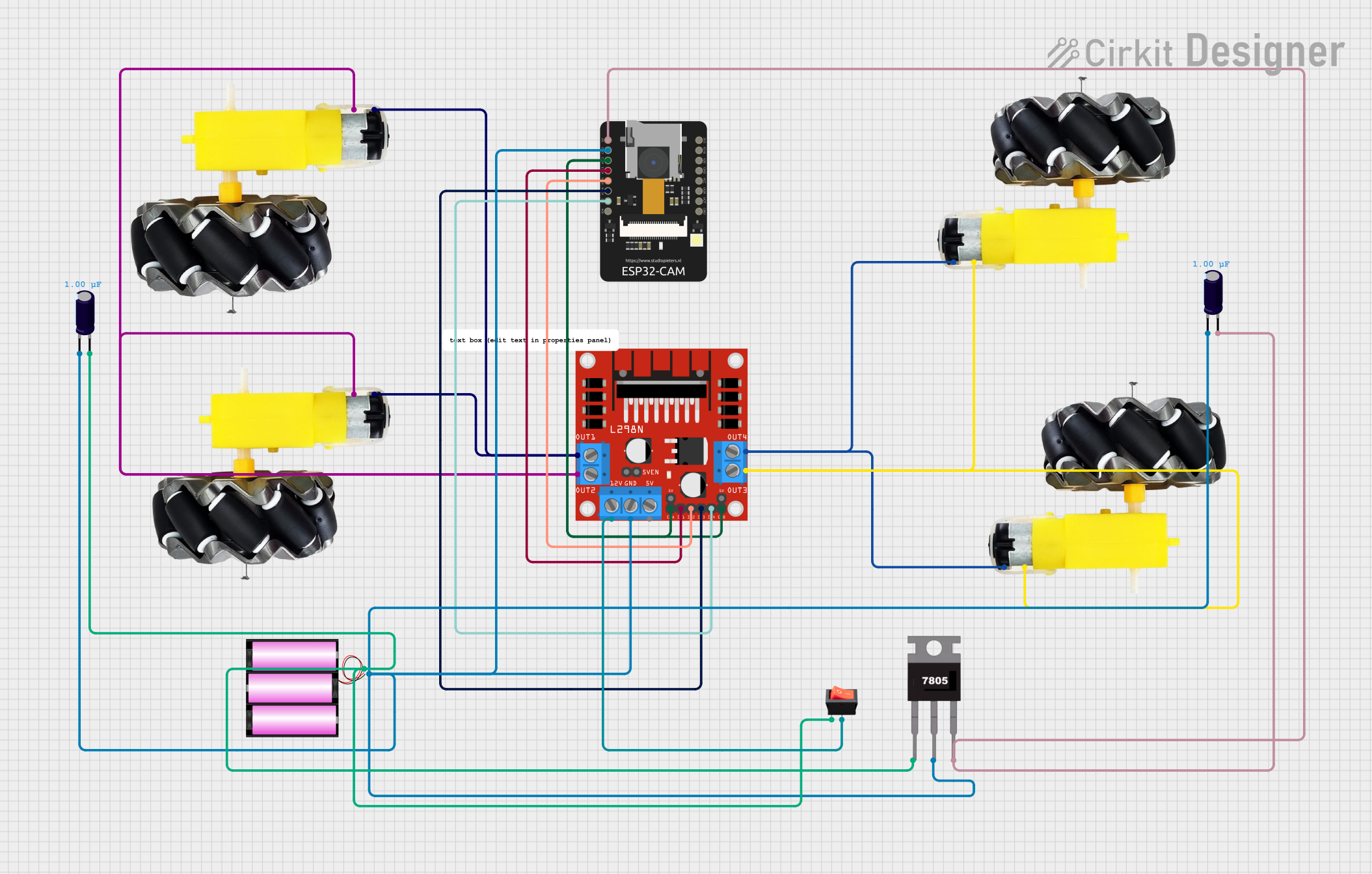
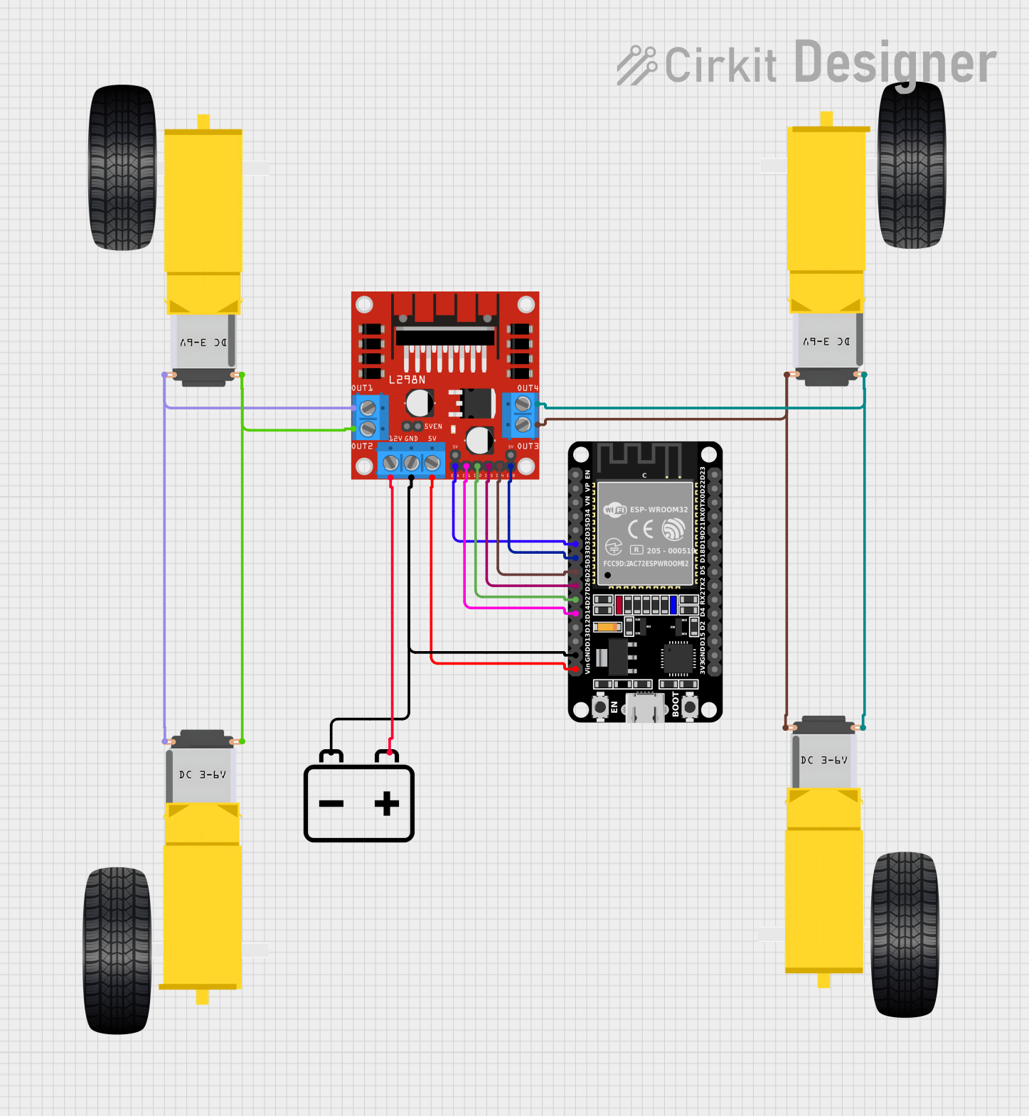
How to Use the Component in a Circuit

  1. Power Connections: Connect the motor power supply to the VCC and GND pins, ensuring the voltage is within the specified range.
  2. Motor Connections: Attach the motor leads to the A+ and A- pins (and B+ and B- if using a bipolar stepper motor).
  3. Control Connections: Connect the PWM pin to a PWM-capable pin on your microcontroller for speed control. The DIR pin determines the motor's direction, and the EN pin can be used to enable or disable the motor driver.

Important Considerations and Best Practices

  • Ensure the power supply can handle the motor's current requirements.
  • Use appropriate flyback diodes to protect against voltage spikes when driving inductive loads.
  • Avoid running the motor driver at its peak current for extended periods to prevent overheating.
  • Implement proper heat dissipation techniques if operating near the maximum current rating.

Example Code for Arduino UNO

// Define motor driver control pins
const int pwmPin = 3; // PWM input for speed control
const int dirPin = 4; // Direction control input
const int enPin = 5;  // Enable input for the motor driver

void setup() {
  // Set motor driver pins as outputs
  pinMode(pwmPin, OUTPUT);
  pinMode(dirPin, OUTPUT);
  pinMode(enPin, OUTPUT);

  // Enable the motor driver
  digitalWrite(enPin, HIGH);
}

void loop() {
  // Set motor direction to clockwise
  digitalWrite(dirPin, HIGH);
  // Set motor speed to 50% duty cycle
  analogWrite(pwmPin, 127);
  delay(2000);

  // Set motor direction to counter-clockwise
  digitalWrite(dirPin, LOW);
  // Set motor speed to 75% duty cycle
  analogWrite(pwmPin, 191);
  delay(2000);
}

Troubleshooting and FAQs

Common Issues

  • Motor not running: Check power supply connections and ensure the EN pin is set high.
  • Motor running hot: Ensure the current draw is within the driver's limits and improve cooling.
  • Inconsistent motor speed: Verify the PWM signal is stable and within the correct voltage range.

Solutions and Tips

  • Use a multimeter to check connections and signal levels.
  • Implement a soft start mechanism to reduce inrush current.
  • If using long wires, consider using twisted pairs to reduce electromagnetic interference.

FAQs

Q: Can I drive two motors with this motor driver? A: Yes, the Cytron 2020 motor driver can control two motors if they are within the current and voltage specifications.

Q: What is the maximum frequency for the PWM input? A: The maximum recommended frequency for the PWM input is 25kHz.

Q: How do I reverse the motor direction? A: Change the logic level of the DIR pin to reverse the motor's direction.

Q: Can I use this motor driver with a microcontroller that operates at 3.3V logic? A: Yes, the control signal input is TTL compatible and can accept 3.3V logic levels.