
How to Use Breakout Board for Electret Microphone: Examples, Pinouts, and Specs
 Design with Breakout Board for Electret Microphone in Cirkit Designer
Introduction
The SparkFun Breakout Board for Electret Microphone is a compact and user-friendly module designed to simplify the integration of an electret microphone into your electronic projects. This breakout board includes essential components such as resistors and capacitors to condition the microphone's output signal, making it suitable for direct interfacing with microcontrollers, audio processing circuits, or other analog input systems.
Explore Projects Built with Breakout Board for Electret Microphone
 Open Project in Cirkit Designer
 Open Project in Cirkit Designer
 Open Project in Cirkit Designer
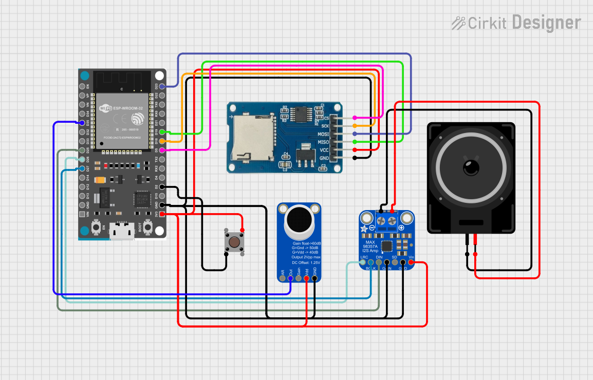 Open Project in Cirkit Designer
Explore Projects Built with Breakout Board for Electret Microphone
Open Project in Cirkit DesignerOpen Project in Cirkit DesignerOpen Project in Cirkit DesignerOpen Project in Cirkit DesignerCommon Applications and Use Cases
- Voice recognition systems
- Audio recording and processing
- Sound level detection
- DIY audio projects
- Environmental sound monitoring
Technical Specifications
The SparkFun Breakout Board for Electret Microphone is designed to provide a clean and amplified analog signal from the microphone. Below are the key technical details:
Key Specifications
| Parameter | Value |
|---|---|
| Operating Voltage | 1.5V to 5V |
| Output Signal Type | Analog |
| Gain | Adjustable via onboard potentiometer |
| Frequency Response | 20 Hz to 20 kHz |
| Microphone Type | Electret |
| Dimensions | 25.4mm x 25.4mm (1" x 1") |
Pin Configuration and Descriptions
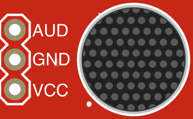
| Pin Name | Description |
|---|---|
| VCC | Power supply input (1.5V to 5V). Connect to the positive voltage source. |
| GND | Ground connection. Connect to the ground of your circuit. |
| OUT | Analog output signal. Connect to an analog input pin of a microcontroller. |
Usage Instructions
How to Use the Component in a Circuit
- Power the Breakout Board: Connect the
VCCpin to a power source (1.5V to 5V) and theGNDpin to the ground of your circuit. - Connect the Output: Use the
OUTpin to send the analog signal to an analog input pin of your microcontroller or an audio processing circuit. - Adjust the Gain: Use the onboard potentiometer to adjust the gain of the microphone signal. Turn the potentiometer clockwise to increase the gain and counterclockwise to decrease it.
- Filter the Signal (Optional): If needed, add external filtering components to further condition the signal for your specific application.
Important Considerations and Best Practices
- Power Supply: Ensure the power supply voltage is within the specified range (1.5V to 5V) to avoid damaging the board.
- Signal Noise: Keep the breakout board away from high-frequency noise sources to maintain signal integrity.
- Gain Adjustment: Start with a low gain setting and gradually increase it to avoid signal clipping or distortion.
- Microphone Placement: Position the microphone in a location that minimizes unwanted noise and interference.
Example: Connecting to an Arduino UNO
Below is an example of how to connect the SparkFun Breakout Board for Electret Microphone to an Arduino UNO and read the analog signal.
Circuit Connections
- Connect the
VCCpin of the breakout board to the 5V pin of the Arduino. - Connect the
GNDpin of the breakout board to the GND pin of the Arduino. - Connect the
OUTpin of the breakout board to the A0 analog input pin of the Arduino.
Arduino Code
// Example code to read the analog signal from the electret microphone breakout board
// and print the values to the Serial Monitor.

const int micPin = A0; // Define the analog pin connected to the microphone output

void setup() {
  Serial.begin(9600); // Initialize serial communication at 9600 baud
}

void loop() {
  int micValue = analogRead(micPin); // Read the analog value from the microphone
  Serial.println(micValue);         // Print the value to the Serial Monitor
  delay(10);                        // Small delay to stabilize readings
}
Troubleshooting and FAQs
Common Issues and Solutions
No Output Signal
- Cause: Incorrect wiring or insufficient power supply.
- Solution: Double-check all connections and ensure the power supply voltage is within the specified range.
Distorted or Clipped Signal
- Cause: Gain is set too high.
- Solution: Adjust the onboard potentiometer to reduce the gain.
Low Signal Amplitude
- Cause: Gain is set too low or the microphone is too far from the sound source.
- Solution: Increase the gain using the potentiometer or move the microphone closer to the sound source.
Excessive Noise in the Signal
- Cause: Electrical interference or poor grounding.
- Solution: Ensure proper grounding and keep the breakout board away from noise sources such as motors or high-frequency circuits.
FAQs
Q: Can I use this breakout board with a 3.3V microcontroller?
A: Yes, the breakout board operates within a voltage range of 1.5V to 5V, making it compatible with 3.3V systems.
Q: How do I know if the microphone is working?
A: Connect the breakout board to a microcontroller and monitor the analog output signal. You should see variations in the signal when sound is present.
Q: Can I use this breakout board for audio recording?
A: Yes, the breakout board provides a conditioned analog signal suitable for audio recording applications. However, additional amplification or filtering may be required depending on your specific needs.
Q: Is the gain adjustment potentiometer necessary to use?
A: While not mandatory, adjusting the gain allows you to optimize the signal level for your application, ensuring better performance.