
How to Use MIDI_CONN_FEMALE_SUPPORT: Examples, Pinouts, and Specs
 Design with MIDI_CONN_FEMALE_SUPPORT in Cirkit Designer
Introduction
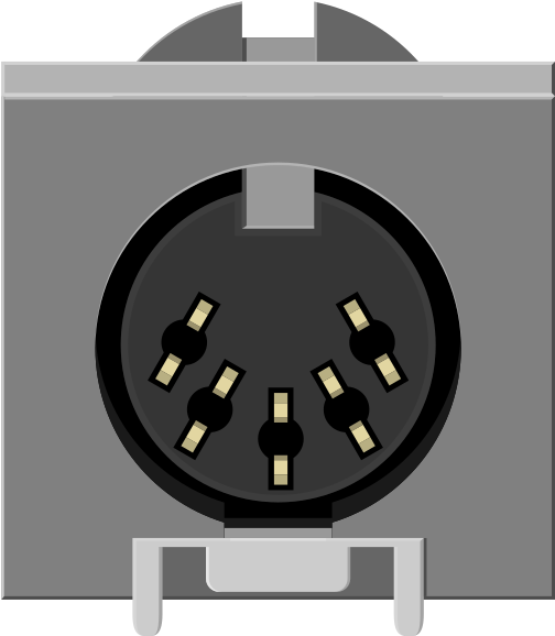
The MIDI_CONN_FEMALE_SUPPORT is a female MIDI connector manufactured by SparkFun, designed to interface with MIDI (Musical Instrument Digital Interface) devices. This component facilitates the transmission of musical data and control signals, making it an essential part of MIDI-based systems. It is commonly used in audio equipment, synthesizers, MIDI controllers, and other devices requiring MIDI communication.
Explore Projects Built with MIDI_CONN_FEMALE_SUPPORT
 Open Project in Cirkit Designer
 Open Project in Cirkit Designer
 Open Project in Cirkit Designer
 Open Project in Cirkit Designer
Explore Projects Built with MIDI_CONN_FEMALE_SUPPORT
Open Project in Cirkit DesignerOpen Project in Cirkit DesignerOpen Project in Cirkit DesignerOpen Project in Cirkit DesignerCommon Applications
- Connecting MIDI controllers to synthesizers or audio interfaces
- Building custom MIDI devices or circuits
- Repairing or upgrading existing MIDI hardware
- Prototyping MIDI-based projects with microcontrollers like Arduino
Technical Specifications
Key Technical Details
| Parameter | Value |
|---|---|
| Manufacturer | SparkFun |
| Part ID | MIDI_CONN_FEMALE_SUPPORT |
| Connector Type | 5-pin DIN Female |
| Voltage Rating | 5V (typical for MIDI signals) |
| Current Rating | 5mA (typical MIDI operation) |
| Mounting Style | Through-hole |
| Dimensions | 15.5mm x 12.5mm x 10mm |
| Material | Plastic housing with metal pins |
Pin Configuration and Descriptions
The MIDI_CONN_FEMALE_SUPPORT has five pins arranged in a standard 5-pin DIN configuration. Below is the pinout and description:
| Pin Number | Name | Description |
|---|---|---|
| 1 | Shield | Ground connection for shielding and noise reduction |
| 2 | Not Connected | Typically unused in standard MIDI applications |
| 3 | Not Connected | Typically unused in standard MIDI applications |
| 4 | MIDI Out (+) | Positive signal line for MIDI data transmission |
| 5 | MIDI Out (-) | Negative signal line for MIDI data transmission (complementary to Pin 4) |
Note: Pins 2 and 3 are not used in most MIDI implementations but may be repurposed in custom designs.
Usage Instructions
How to Use the Component in a Circuit
Mounting the Connector:
- Solder the MIDI_CONN_FEMALE_SUPPORT onto a PCB using its through-hole pins. Ensure proper alignment with the circuit design.
- Use a PCB footprint that matches the connector's pin spacing and dimensions.
Connecting to a MIDI Circuit:
- Connect Pin 4 (MIDI Out +) to the MIDI signal line through a 220-ohm resistor.
- Connect Pin 5 (MIDI Out -) to the complementary signal line through another 220-ohm resistor.
- Connect Pin 1 (Shield) to the circuit ground for proper shielding.
Interfacing with Microcontrollers:
- Use an optocoupler to isolate the MIDI input signal from the microcontroller.
- Ensure the circuit complies with the MIDI standard (5V signal levels and 31.25 kbps baud rate).
Important Considerations and Best Practices
- Signal Integrity: Use shielded cables to minimize noise and interference in MIDI communication.
- Power Supply: Ensure the circuit operates at the standard 5V level for MIDI signals.
- Isolation: Always use an optocoupler when interfacing with microcontrollers to protect against voltage spikes.
- Pin Orientation: Double-check the pin configuration before soldering or connecting to avoid miswiring.
Example: Connecting to an Arduino UNO
Below is an example of how to connect the MIDI_CONN_FEMALE_SUPPORT to an Arduino UNO for receiving MIDI signals:
Circuit Diagram
- Pin 4 (MIDI Out +) → 220-ohm resistor → Optocoupler input
- Pin 5 (MIDI Out -) → 220-ohm resistor → Optocoupler input
- Pin 1 (Shield) → Ground
Arduino Code
// MIDI Receiver Example for Arduino UNO
// This code reads MIDI messages and prints them to the Serial Monitor.

#include <MIDI.h> // Include the MIDI library

MIDI_CREATE_DEFAULT_INSTANCE();

void setup() {
  Serial.begin(31250); // Set MIDI baud rate
  MIDI.begin(MIDI_CHANNEL_OMNI); // Listen to all MIDI channels
  Serial.println("MIDI Receiver Initialized");
}

void loop() {
  if (MIDI.read()) {
    // If a MIDI message is received, print its type and data
    Serial.print("MIDI Message Type: ");
    Serial.println(MIDI.getType());
    Serial.print("Data1: ");
    Serial.println(MIDI.getData1());
    Serial.print("Data2: ");
    Serial.println(MIDI.getData2());
  }
}
Note: Ensure the MIDI library is installed in your Arduino IDE before uploading the code.
Troubleshooting and FAQs
Common Issues
No MIDI Signal Detected:
- Cause: Incorrect wiring or missing resistors.
- Solution: Verify the pin connections and ensure the 220-ohm resistors are in place.
Noise or Interference in MIDI Communication:
- Cause: Unshielded cables or improper grounding.
- Solution: Use shielded cables and connect Pin 1 (Shield) to ground.
Microcontroller Not Responding to MIDI Messages:
- Cause: Missing optocoupler or incorrect baud rate.
- Solution: Add an optocoupler for isolation and set the baud rate to 31.25 kbps.
FAQs
Q: Can this connector be used for non-MIDI applications?
A: Yes, the 5-pin DIN connector can be repurposed for other applications, but ensure the pinout matches your requirements.
Q: Is this connector compatible with 3.3V systems?
A: While MIDI typically operates at 5V, you can use level shifters to interface with 3.3V systems.
Q: How do I test if the connector is working?
A: Use a multimeter to check continuity between the pins and ensure proper soldering. Additionally, test the circuit with a known MIDI device.
This concludes the documentation for the MIDI_CONN_FEMALE_SUPPORT. For further assistance, refer to SparkFun's official resources or contact their support team.