
How to Use BadgerStick: Examples, Pinouts, and Specs
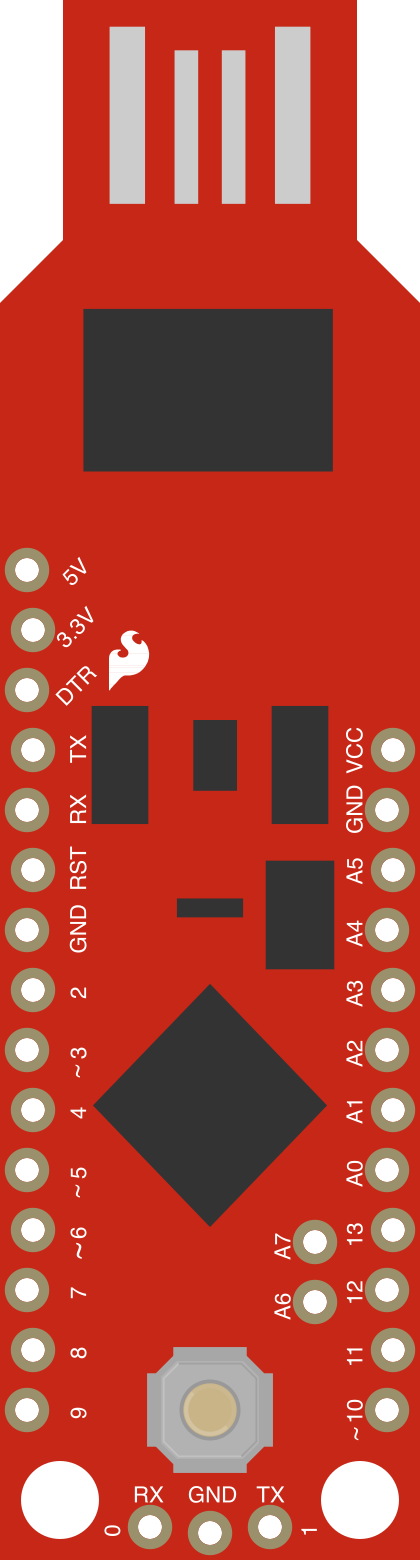
 Design with BadgerStick in Cirkit Designer
Introduction
The BadgerStick, manufactured by SparkFun Electronics, is a versatile microcontroller board designed for easy integration with various sensors and actuators. It is ideal for DIY electronics projects, rapid prototyping, and educational purposes. The compact design and user-friendly features make it an excellent choice for beginners and experienced developers alike.
Explore Projects Built with BadgerStick
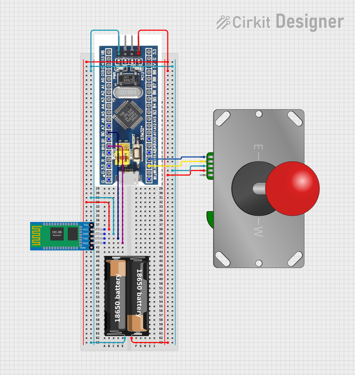 Open Project in Cirkit Designer
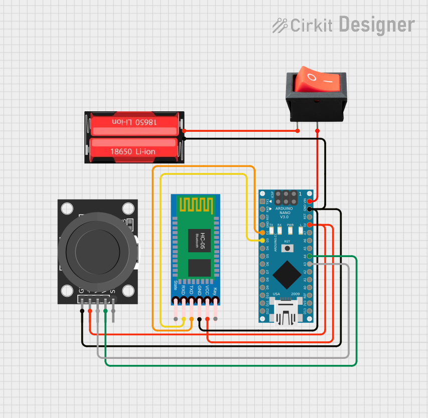 Open Project in Cirkit Designer
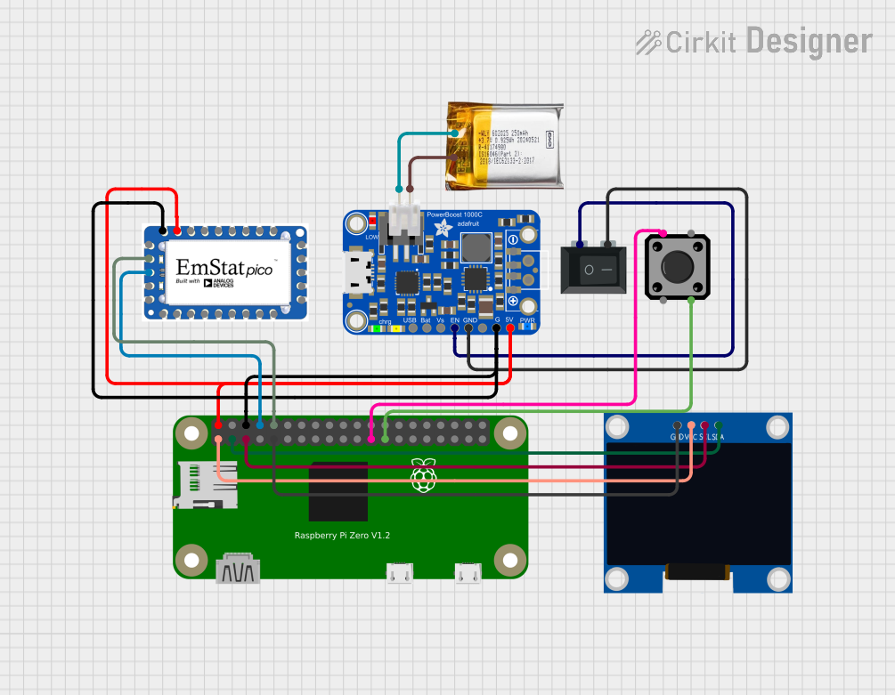 Open Project in Cirkit Designer
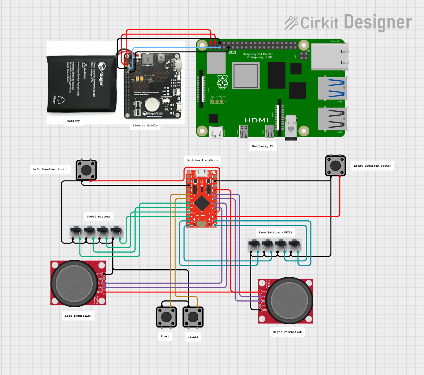 Open Project in Cirkit Designer
Explore Projects Built with BadgerStick
Open Project in Cirkit DesignerOpen Project in Cirkit DesignerOpen Project in Cirkit DesignerOpen Project in Cirkit DesignerCommon Applications and Use Cases
- Prototyping IoT (Internet of Things) devices
- Interfacing with sensors and actuators
- Educational projects for learning microcontroller programming
- Wearable electronics and compact embedded systems
- Rapid development of small-scale automation systems
Technical Specifications
The BadgerStick is based on the ARM Cortex-M0+ architecture, offering a balance of performance and low power consumption. Below are the key technical details:
Key Technical Details
| Specification | Value |
|---|---|
| Microcontroller | ATSAMD21E18A (ARM Cortex-M0+) |
| Operating Voltage | 3.3V |
| Input Voltage (USB) | 5V |
| Flash Memory | 256 KB |
| SRAM | 32 KB |
| Clock Speed | 48 MHz |
| Digital I/O Pins | 14 |
| PWM Pins | 6 |
| Analog Input Pins | 6 |
| Communication Interfaces | I2C, SPI, UART |
| USB Interface | Micro-USB |
| Dimensions | 2.0" x 0.7" (50.8mm x 17.8mm) |
Pin Configuration and Descriptions
The BadgerStick features a simple pinout for easy integration with external components. Below is the pin configuration:
| Pin Number | Pin Name | Description |
|---|---|---|
| 1 | GND | Ground pin |
| 2 | 3.3V | 3.3V power output |
| 3 | A0 | Analog input pin 0 |
| 4 | A1 | Analog input pin 1 |
| 5 | D0 | Digital I/O pin 0 |
| 6 | D1 | Digital I/O pin 1 |
| 7 | D2 | Digital I/O pin 2 (PWM capable) |
| 8 | D3 | Digital I/O pin 3 (PWM capable) |
| 9 | SDA | I2C data line |
| 10 | SCL | I2C clock line |
| 11 | MOSI | SPI Master Out Slave In |
| 12 | MISO | SPI Master In Slave Out |
| 13 | SCK | SPI clock |
| 14 | RST | Reset pin |
Usage Instructions
How to Use the BadgerStick in a Circuit
Powering the Board:
- Connect the BadgerStick to a computer or USB power source using a Micro-USB cable.
- Alternatively, supply 3.3V to the 3.3V pin and GND to the GND pin.
Programming the Board:
- The BadgerStick is compatible with the Arduino IDE. Install the necessary board definitions by adding the SparkFun SAMD Boards package via the Arduino Board Manager.
- Select "SparkFun BadgerStick" as the board in the Arduino IDE.
Connecting Sensors and Actuators:
- Use the digital and analog pins to interface with sensors and actuators.
- For I2C devices, connect the SDA and SCL pins to the corresponding pins on the sensor or module.
- For SPI devices, connect MOSI, MISO, and SCK pins, along with a chip select (CS) pin.
Uploading Code:
- Write your code in the Arduino IDE and upload it to the BadgerStick via the Micro-USB connection.
Important Considerations and Best Practices
- Ensure that the input voltage does not exceed 3.3V on any pin to avoid damaging the microcontroller.
- Use appropriate pull-up resistors for I2C communication if the connected devices do not have built-in pull-ups.
- Avoid drawing more current than the board's maximum output capability (50mA on the 3.3V pin).
- Use decoupling capacitors when connecting external components to reduce noise and improve stability.
Example Code for Arduino UNO Integration
Below is an example of how to use the BadgerStick to read an analog sensor value and control an LED:
// Define pin connections
const int sensorPin = A0; // Analog sensor connected to A0
const int ledPin = D3;    // LED connected to digital pin D3

void setup() {
  pinMode(ledPin, OUTPUT); // Set LED pin as output
  Serial.begin(9600);      // Initialize serial communication
}

void loop() {
  int sensorValue = analogRead(sensorPin); // Read sensor value
  Serial.print("Sensor Value: ");
  Serial.println(sensorValue); // Print sensor value to Serial Monitor

  // Map sensor value to PWM range (0-255) and write to LED
  int ledBrightness = map(sensorValue, 0, 1023, 0, 255);
  analogWrite(ledPin, ledBrightness);

  delay(100); // Small delay for stability
}
Troubleshooting and FAQs
Common Issues and Solutions
The board is not recognized by the computer:
- Ensure the USB cable is functional and supports data transfer.
- Check that the correct board and port are selected in the Arduino IDE.
Code upload fails:
- Verify that the BadgerStick is in bootloader mode by double-tapping the reset button.
- Ensure the SparkFun SAMD Boards package is installed in the Arduino IDE.
Sensors or actuators are not responding:
- Double-check the wiring and ensure proper connections.
- Confirm that the sensor or actuator is compatible with 3.3V logic levels.
I2C devices are not detected:
- Use a pull-up resistor (4.7kΩ to 10kΩ) on the SDA and SCL lines if necessary.
- Verify the I2C address of the device and ensure it matches the code.
FAQs
Q: Can the BadgerStick be powered by a battery?
A: Yes, you can power the BadgerStick using a 3.3V battery connected to the 3.3V and GND pins.
Q: Is the BadgerStick compatible with Arduino libraries?
A: Yes, the BadgerStick is compatible with most Arduino libraries, especially those designed for SAMD-based boards.
Q: How do I reset the BadgerStick?
A: Press the reset button once to restart the board. Double-tap the reset button to enter bootloader mode for firmware updates.
Q: Can I use the BadgerStick for low-power applications?
A: Yes, the ARM Cortex-M0+ processor is optimized for low-power operation, making it suitable for battery-powered projects.