How to Use flow rate sensor: Examples, Pinouts, and Specs
Introduction
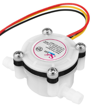
A flow rate sensor is an electronic device designed to measure the rate at which a fluid (liquid or gas) flows through a system. These sensors are critical in various applications such as water management systems, HVAC (Heating, Ventilation, and Air Conditioning), medical equipment, and industrial processes where precise fluid control is necessary.
Explore Projects Built with flow rate sensor
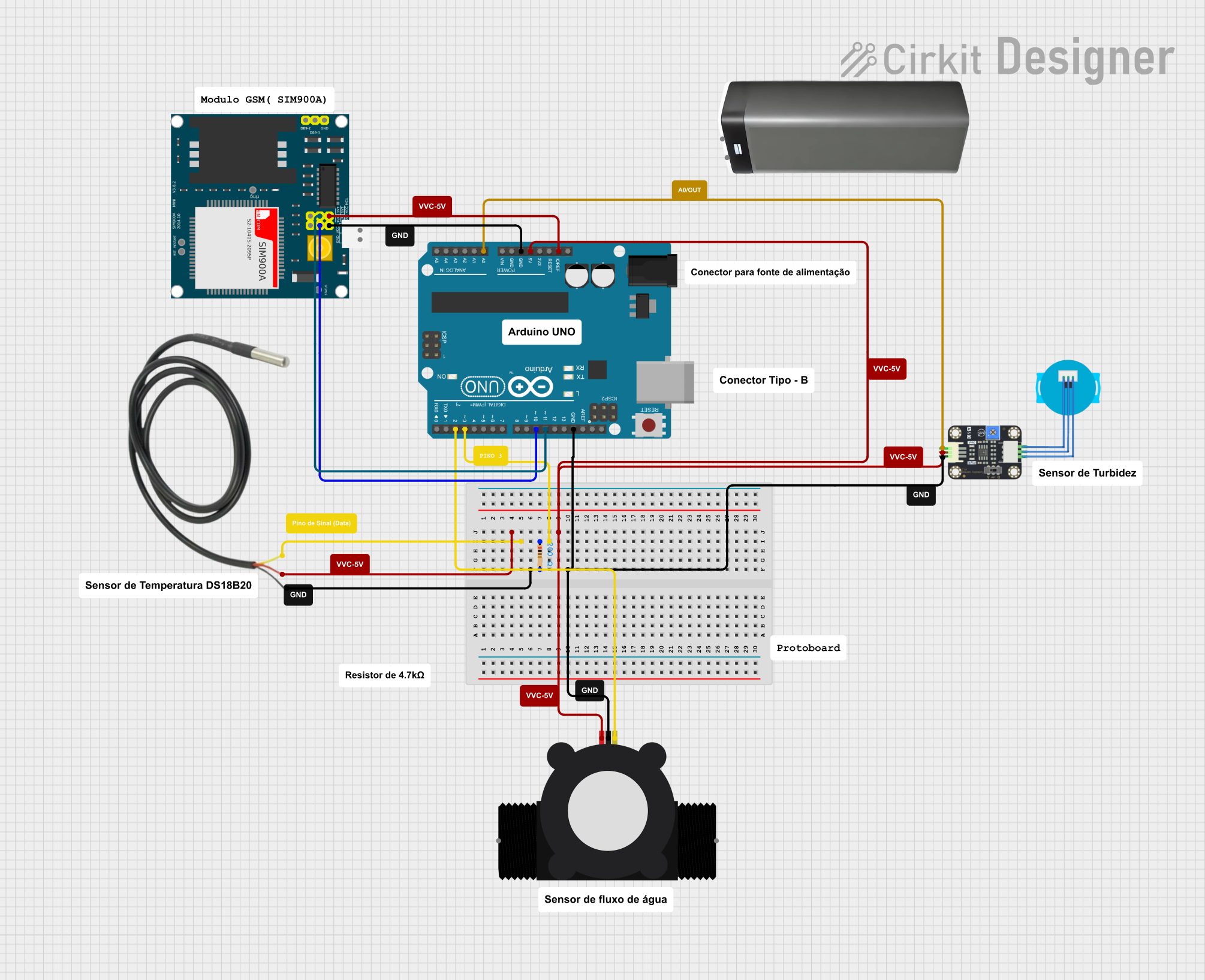
Explore Projects Built with flow rate sensor
Common Applications and Use Cases
- Monitoring and controlling water flow in irrigation systems.
- Measuring fuel consumption in automotive and aerospace industries.
- Managing flow rates in chemical processing plants.
- Ensuring accurate dosing in pharmaceutical production.
- Flow measurement in beverage and food production lines.
Technical Specifications
Key Technical Details
- Voltage: Typically 5V to 24V DC
- Current: Depends on model, often in the range of 10-100 mA
- Output: Pulse signal proportional to flow rate
- Flow Rate Range: Varies by model, e.g., 1-30 liters per minute (L/min)
- Accuracy: ±1-5% of reading (model dependent)
- Operating Temperature Range: 0°C to 80°C (32°F to 176°F)
Pin Configuration and Descriptions
| Pin Number | Description | Notes |
|---|---|---|
| 1 | Vcc (Power Supply) | Connect to 5V-24V DC |
| 2 | Ground (GND) | Connect to system ground |
| 3 | Signal Output | Outputs pulse signal |
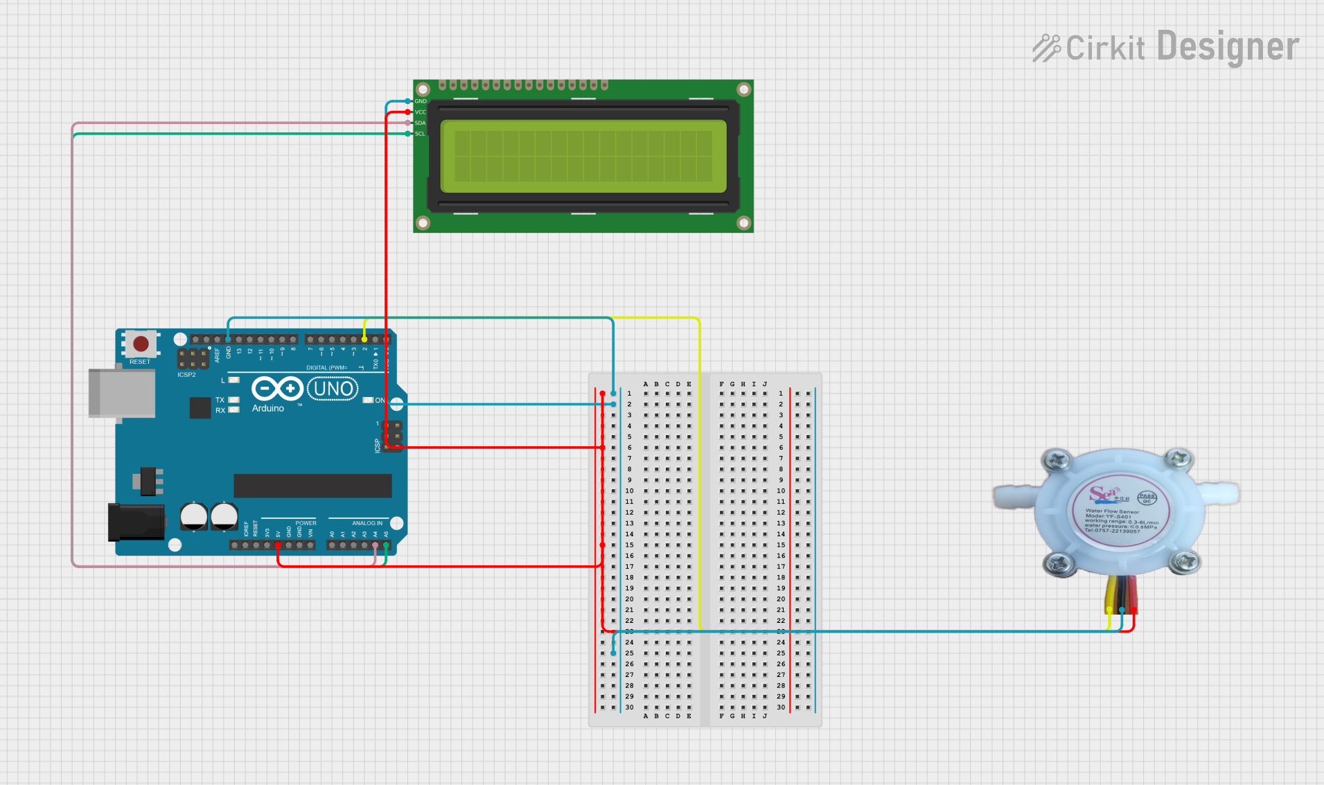
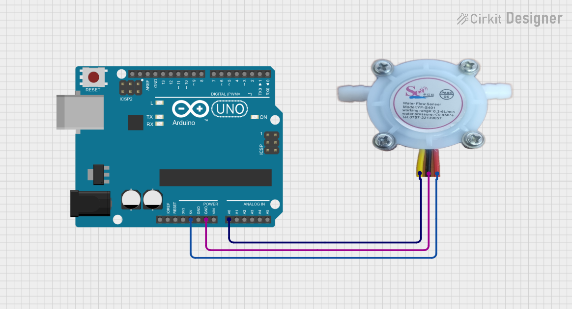
Usage Instructions
How to Use the Component in a Circuit
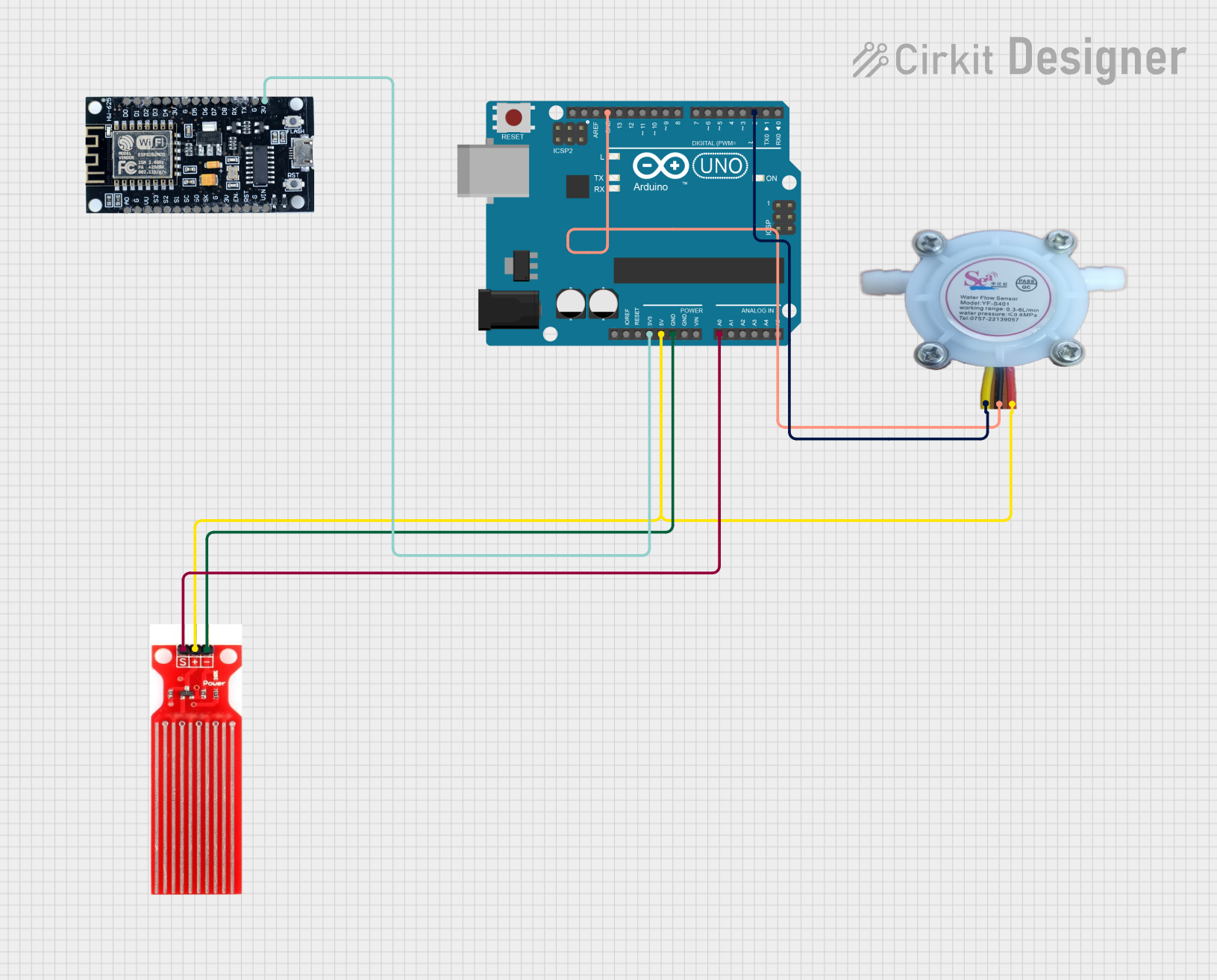
- Power Supply: Connect the Vcc pin to a suitable power supply (5V-24V DC) and the GND pin to the system ground.
- Signal Output: Connect the signal output pin to a microcontroller or any other device capable of reading pulse signals.
- Mounting: Secure the sensor in place ensuring the flow direction matches the arrow on the sensor body.
Important Considerations and Best Practices
- Ensure the liquid or gas is clean and free from particles that could clog or damage the sensor.
- Avoid subjecting the sensor to flow rates beyond its specified range to prevent damage.
- Use appropriate fittings and seals to prevent leaks at the connection points.
- Calibrate the sensor if necessary to ensure accurate readings.
Example Code for Arduino UNO
// Define the pin connected to the flow rate sensor
const int flowSensorPin = 2;

// Variables to store the pulse count and flow rate
volatile int pulseCount;
float flowRate;
unsigned long lastFlowRateCheck = 0;

// Interrupt Service Routine for the flow sensor
void flow() {
  pulseCount++;
}

void setup() {
  // Initialize a serial connection for reporting values
  Serial.begin(9600);

  // Set up the flow sensor pin as an input
  pinMode(flowSensorPin, INPUT_PULLUP);

  // Attach the interrupt function to the sensor pin
  attachInterrupt(digitalPinToInterrupt(flowSensorPin), flow, RISING);
}

void loop() {
  if ((millis() - lastFlowRateCheck) > 1000) { // Only process every second
    // Disable the interrupt while calculating flow rate
    detachInterrupt(digitalPinToInterrupt(flowSensorPin));

    // Calculate the flow rate in L/min
    // (Pulse frequency (Hz) / 7.5 Q) = flow rate in L/min. (7.5 is a typical K factor)
    flowRate = (pulseCount / 7.5);
    pulseCount = 0; // Reset pulse count for the next second

    // Print the flow rate to the serial monitor
    Serial.print("Flow rate: ");
    Serial.print(flowRate);
    Serial.println(" L/min");

    // Re-enable the interrupt
    attachInterrupt(digitalPinToInterrupt(flowSensorPin), flow, RISING);

    lastFlowRateCheck = millis();
  }
}
Code Comments
- The
flowSensorPinvariable defines the pin to which the flow sensor is connected. pulseCountis incremented by the interrupt service routineflow()each time the sensor sends a pulse.- The
flowRateis calculated once every second based on the number of pulses counted. - The
lastFlowRateCheckvariable ensures that the flow rate is updated every second. - The
detachInterruptandattachInterruptfunctions are used to safely calculate the flow rate without missing pulses.
Troubleshooting and FAQs
Common Issues
- Inaccurate Readings: Ensure the sensor is properly calibrated and free from debris.
- No Output Signal: Check the wiring and power supply. Ensure the sensor is not damaged.
- Erratic Readings: Verify that there are no air bubbles in the fluid and that the sensor is fully submerged.
Solutions and Tips for Troubleshooting
- Regularly inspect and clean the sensor to prevent clogging.
- Use a debouncing algorithm or hardware debouncing if the output signal is noisy.
- If the sensor is not responding, replace it and check the rest of the circuit for issues.
FAQs
Q: Can the flow rate sensor be used with liquids other than water? A: Yes, but ensure the sensor is compatible with the specific liquid in terms of material and operating range.
Q: How do I calibrate the flow rate sensor? A: Calibration typically involves comparing the sensor output with a known flow rate and adjusting the calculation accordingly.
Q: What is the maximum distance the sensor can be placed from the microcontroller? A: This depends on the sensor's output signal strength and the quality of the wiring. Use shielded cables for long distances to minimize signal degradation.